0020008153-05 11.05 Instructions for Use Installation and Servicing 12hxi 15hxi G.C. No. 41-047-73 G.C. No. 41-047-74 18hxi 24hxi G.C. No. 41-047-63 G.C. No. 41-047-69 30hxi 38hxi G.C. No. 41-047-64 G.C. No. 41-047-71 High Efficiency Condensing Boilers Glow-worm, Nottingham Road, Belper, Derbyshire. DE56 1JT www.glow-worm.co.
Guarantee Registration Thank you for installing a new Glow-worm appliance in your home. Glow-worm appliances are manufactured to the very highest standard so we are pleased to offer our customers a Comprehensive Guarantee. This product is guaranteed for 24 months from the date of installation or 30 months from the date of manufacture, whichever is the shorter, for parts.
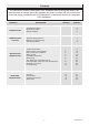
Contents The instructions consist of three parts, User, Installation and Servicing Instructions.The instructions are an integral part of the appliance and must, to comply with the current issue of the Gas Safety (Installation and Use) Regulations, be handed to the user on completion of the installation. CONTENTS INTRODUCTION INSTRUCTIONS FOR USE INSTALLATION INSTRUCTIONS SERVICING INSTRUCTIONS DESCRIPTION SECTION PAGE No.
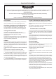
Important Information WARNINGS Gas Leak or Fault Turn off the gas emergency control valve immediately. Eliminate all sources of ignition, i.e.smoking, blowlamps, hot air guns etc. Do not operate electrical lights or switches either on or off. Open all doors and windows, ventilate the area. Sheet Metal Parts This boiler contains metal parts (components) and care should be taken when handling and cleaning, with particular regard to edges.
General Information General Note Condensate Drain This boiler is designed to provide central heating from a fully pumped open-vented or sealed water system with a fully indirect cylinder. The condensate drain, see section 7.3, must not be modified or blocked. Pluming from flue terminal Once the controls are set the boiler operates automatically. Like all condensing boilers this appliance will produce a plume of condensation from the flue terminal in cool weather.
Manual Handling Carriage of carton from point of delivery to point of installation – first or higher floor, cellar. Positioning of Appliance for Final Installation – above worktop, foreseeable obstructions etc. Recommend 2-person lift or 1 person with use of sack truck. If 1 person is performing lift, straddle the load, tilt and place carton into position on truck. Recommend secure appliance onto truck with suitable straps. Ensure safe lifting techniques are used – keep back straight – bend using legs.
Appliance Safety Devices - User Instructions Electrical Supply Failure Reset Switch The boiler will not work without an electrical supply. Normal operation of the boiler should resume when the electrical supply is restored. Reset any external controls, to resume normal operation of the central heating. If the boiler does not resume normal operation turn the mains reset switch off and on. If the boiler does not resume normal operation after this the overheat stat may have operated.
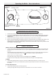
CONTROLS FASCIA MAINS RESET SWITCH CONTROL LIGHT CENTRAL HEATING WATER TEMPERATURE CONTROL 9239 Operating the Boiler - User Instructions DIGITAL DISPLAY Diagram 1 OPERATION OF THE BOILER 1. Check that all isolating valves on the boiler are open and that water flows from the hot water tap. 2. If you are in any doubt about the boiler being filled with water contact your installer or Glow-worm's own service organisation using the telephone number on the inside front cover of this booklet.
1 Technical Information 1.1 IMPORTANT NOTICE Certification The boiler is supplied in one carton, which includes a fittings and documentation pack. This boiler certificated to the current issue of EN 483 for performance and safety. This boiler is for use only on G20 natural gas, but the 30hxi may be converted for use on G31 gas (Propane L.P.G.). It is important that no alteration is made to the boiler, without permission, in writing, from Glow-worm.
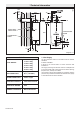
600 MAX. 87 MIN. 12856 1 Technical Information 334 48 176 113.5 53 66 INSIDE WALL FIXING FACE 33 CONDENSATE DRAIN 600 CONDENSATE DRAIN 133 30 13 GAS 54 48 375 73 Diagram 1.1 1.3 Gas Supply TABLE 1 TOTAL WEIGHT GAS CONNECTION Rc1/2 (1/2in BSPT) WATER CONNECTION 22mm. copper ELECTRICITY SUPPLY 230V~50Hz fused 3A ELECTRICAL RATING 60W INTERNAL FUSE RATE Main PCB 630mAT 0020008153-05 The gas installation shall be in accordance with the relevant standards.
1 Technical Information TABLE 2 (cont'd) TABLE 2 12 hxi BURNER Case Off %CO2 Case On 3 APPROXIMATE m /h GAS RATE 3 (after 10 mins. ft /h from cold) 30 hxi 9.1 +0.2 -0.5 BURNER Case Off %CO2 Case On 9.3 +0.3 -0.5 MIN MAX 0.53 1.29 18.7 45.6 9.1 +0.2 -0.5 BURNER Case Off %CO2 Case On 9.3 +0.3 -0.5 MAX 0.53 1.61 18.7 57.0 APPROXIMATE m3/h GAS RATE (after 10 mins. ft3/h from cold) 107 8.8 +0.2 -0.5 9.0 +0.3 -0.5 MAX 0.67 4.06 23.
330 11975 12327 12335 12336 12334 1 Technical Information Diagram 1.
2 Boiler Location and Ventilation 12344 2.1 Boiler Location This boiler is not suitable for outdoor installation. This boiler may be installed in any room, although particular attention is drawn to the installation of a boiler in a room containing a bath or shower where reference must be made to the relevant requirements. 5 5 This boiler is suitable for installation in bathroom zones 2 and 3. In GB this is the current I.E.E. WIRING REGULATIONS and BUILDING REGULATIONS.
3 Flue Location and Ventilation 3.1 Flue Options 3.2 Flue Length This boiler is suitable for concentric Horizontal and Vertical flues, elevated horizontal and vertical twin, all are fitted onto the top of the boiler. The maximum permissable horizontal flue length is 10 metres plus the flue terminal, this can be achieved by use of the accessories, however should an additional 90o or 2 x 45o elbows be used then the length MUST be reduced by 1metre.
3 Flue Location and Ventilation 3.3 Terminal Position The minimum acceptable siting dimensions for the terminal from obstructions, other terminals and ventilation openings are shown in diagram 3.5. For Ireland the minimum distances for flue terminal positioning must be those detailed in I.S.813 "Domestic Gas Installations". The terminal must be exposed to the external air, allowing free passage of air across it at all times. Being a condensing boiler some pluming may occur from the flue outlet.
12342 4 Water System Diagram 4.
4 Water System 4.1 Draining Tap Table 3. Flow Rate A draining tap must be provided at the lowest point of the system, which will allow the entire system and hot water system to be drained. MODEL MINIMUM FLOW RATE Draining taps shall be to the current issue of BS 2879. 12 hxi 15 hxi 520 litres/hr 646 litres/hr 18 hxi 24 hxi 30 hxi 38 hxi 773.8 litres/hr 500 litres/hr 1220 litres/hr 1633 litres/hr 4.2 Safety Valve A safety valve need not be fitted to an open-vented system. 4.
12999 4 Water System Diagram 4.3 4.5 Bypass 4.8 Combined Feed and Vent A system bypass will be required fitted at least 1.5 metres away from the boiler, refer to the current issue of the central heating system specifications (CHeSS). For combined feed and vent, a 22mm pipe must be fitted in accordance with BS 5449. 4.9 Domestic Hot Water Cylinder 4.
4 Water System 4.11 Sealed water Systems 4.17 Filling a Sealed Water System The installation must comply with the appropriate requirements of the current issue of BS4814, BS5449, BS6759, BS6798 and BS7074 Part 1 and 2. Provision for filling the system at low level must be made, see diagram 4.4. There must be no permanent connection to the mains water supply, even through a non-return valve. See diagram 4.3 for a suggested layout. We do not recommend filling using artificially softened water. 4.
5 Installation Preparation IMPORTANT: With regards to the Health and Safety Manual Handling requirements, two persons shall be required to lift the appliance, refer to manual handling on page 5. SECURING SCREW (2 OFF) RETAINING LUG (2 OFF) 9171 5.1 Appliance Pack NOTE: The fittings pack is located in the base polystyrene packing under the boiler base.
6.1 Hanging Bracket Fixing WALL TEMPLATE If previously removed, reposition the wall template over the flue hole and mark the position of the fixing holes for the hanging bracket, see diagram 6.1. 12047 6 Boiler Fixing Mark and drill the fixing holes and secure the hanging bracket, which is supplied in the polystyrene pack. NOTE: Due to the varied site conditions we do not supply fixings and advise that the installer should supply those which are suitable. HANGING BRACKET 6.
13114 7 Gas, Water and Condensate Connections GAS SERVICE COCK SHOWN IN OPEN POSITION UNION CONNECTOR GAS SERVICE COCK LINER GAS SERVICE COCK SPIGOT COUPLING GAS SUPPLY PIPE IN CONDENSATE DRAIN PIPE Diagram 7.1 9244 7.1 Gas Connection Before connection check the supply of local gas. The gas supply can be connected from below, see diagram 7.1. or through the wall at the rear of the boiler. Refer also to section 1.2 and 1.3. 22mm compression is the recommended fixing for servicing.
13000 7 Gas, Water and Condensate Connections INTERNAL SOIL AND VENT STACK EXTERNAL SOIL AND VENT STACK BOILER BOILER EXTERNAL MAX. 3M Ø22mm MIN. NO RESTRICTION ON LENGTH Ø22mm MIN. NO RESTRICTION ON LENGTH Internal Soil and Vent Pipe External Soil and Vent Pipe or Rainwater Pipe SINK (CONSTITUTES AIR BREAK) BOILER EXTERNAL LENGTH OF PIPE 3M MAX.* Ø22mm MIN. OPEN END OF PIPE DIRECT INTO GULLEY BELOW GROUND BUT ABOVE WATER LEVEL BOILER Ø22mm MIN.
8 Flue Preparation Telescopic and Standard Flue Additional flue accessories are available to suit your site conditions, see diagram 8.2. 8.1 Flue Components The components supplied in the Standard and Telescopic kit are shown in diagram 8.1. Top Outlet Horizontal Concentric Flue Packs: A2043600 Horizontal telescopic flue pack. A2043400 Standard horizontal flue pack.
8 Flue Preparation Telescopic and Standard Flue 8.2 Flue Length Top Side flue - Telescopic - with the flue elbow temporarily fitted, measure the distance from the outside wall to the butt joint, see diagram 8.6. If the measurement 'Y' exceeds 525mm, then the appropriate length of extension pipe is required, if the dimension is less than 320mm DO NOT cut the flue, it can project to a maximum of 600mm, if this is not desirable then a Standard flue MUST be used and cut to length.
8 Flue Preparation Telescopic and Standard Flue 12852 8.2 (cont'd) Flue and Air Ducts Telescopic: The Telescopic Flue system MUST NOT be cut. Adjust the flue to your required length "Y", mark the securing hole position in the air duct. Drill a 3mm diameter hole at this position, take care not to pierce the inner flue duct. Secure with screw provided and tape the joint, see diagram 8.7.
Warning. This boiler must be earthed. RETAINING SCREWS (2) This appliance must be wired in accordance with these instructions. Any fault arising from incorrect wiring cannot be put right under the terms of the Glow-worm guarantee. 12953 9 Electrical Connections All system components must be of an approved type. Electrical components have been tested to meet the equivalent requirements of the BEAB.
9 Electrical Connections 9.2 Electrical connections - testing Carry out preliminary electrical system checks as below: 1. Test insulation resistance to earth of mains cable. 2. Test the earth continuity and short circuit of cables. 3. Test the polarity of the mains. 9.3 Pump Connection Ensure that a seperate pump supply cable is fed to the boiler, see diagram 9.2. Remove connection box, see diagram 9.1.
10.1 Preliminaries - All Systems Remove inner casing panel, see diagram 10.1. A competent person in accordance with the current issue of BS6798 should carry out commissioning. CASING PANEL Make sure that the system has been thoroughly flushed out with cold water. 12354 10 Commissioning INNER CASING PANEL Refill the system with water, making sure that all the air is properly vented from the system and pump, diagram 10.2 shows vent point.
10 Commissioning 10.5 Testing - Gas (Natural Gas only) 10.6 Testing - Heating System Case Off Case On Burner CO2 (G20) 9.1+0.2-0.5 9.3+0.3-0.5 Burner CO2 Propane (G31) 10.5+0.3-0.7 10.7+0.3-0.8 Should any doubt exist about the gas rate, check it using the gas meter test dial and stop watch at least 10 minutes after the burner has lit, making sure that all other gas burning appliances and pilot lights are off. Check that all remote controls are calling for heat. The boiler will fire automatically.
Important Notes SEALING GROMMET To ensure the continued efficient and safe operation of the boiler it is recommended that it is checked and serviced at regular intervals. The frequency of servicing will depend upon the particular installation and usage, but in general once a year should be enough. UNION NUT It is the Law that any servicing is carried out by a competent person.
11 Servicing NOTE: IF THE BURNER HAS TO BE REMOVED IT WILL REQUIRE A NEW GASKET WHEN REFITTED. 11.3 Burner Refer to diagrams, 11.2,11.3,11.4 and 11.5. When replacing the assembly ensure the sealing grommet is correctly fitted. Isolate the gas supply at the gas service cock. Disconnect the gas supply at the gas service cock. NOTE: DO NOT DISCONNECT AT THE GAS VALVE. Remove the two gas pipe bracket securing screws from underside of inner case, see diagram 11.1.
11 Servicing Refer to diagram 11.6 11.4. Combustion Chamber and Heat Exchanger. For adjustment of Propane appliance refer to section 10 (LPG conversion). Refer to diagram 13.3. Remove loose debris from combustion chamber using a soft brush and vacuum cleaner. Carefully flush by spraying water any remaining debris through the condensate trap (Ensure the water is kept away from electrical components). If adjustment proves necessary then proceed as follows. 11.
FLUE ELBOW FRONT CASING PANEL INNER CASING PANEL 9949 12853 11 Servicing COMBUSTION ANALYSER TEST POINT FLUE DUCT EXTENSION Diagram 11.6 SEAL 11407 RETAINING LATCHES Diagram 11.8 11.7 Inner Casing Panel Seal Check. Refer to diagram 11.8. Check the condition of the seal, replace as required. CONTROLS FASCIA USER INTERFACE 11417 To replace remove the old seal, thoroughly clean the casing surfaces. Fit the new seal, it is supplied to the correct length. MIN. SERVICE POTENTIOMETER MAX.
12 Fault Finding 9247 NOTE RETAINING STRAP Before trying to operate the boiler make sure that : • All gas supply cocks are open and that the gas supply has been purged of air. • There is a permanent mains supply to the boiler. • There is a heating demand from the external controls. WARNING. Always isolate the boiler from the electrical supply before carrying out any electrical replacement work. Always check for gas soundness after any service work.
12933 12 Fault Finding Diagram 12.
12191 12 Fault Finding Diagram 12.
12188 12 Fault Finding Diagram 12.
13 Replacement of Parts 13.1 Important Notes 13.3 Igniter Unit When replacing a part on this appliance, use only spare parts that you can be assured conform to the safety and performance specification that we require. Do not use reconditioned or copy parts that have not been clearly authorised by Glow-worm. For access, refer to section 13.1. Replacement of parts must be carried out by a competent person. Remove igniter unit by removing two securing screws.
13 Replacement of Parts 13.5 Gas Valve 11485 GAS MANIFOLD For access, refer to section 13.1. Remove the electrical plug from the gas valve, see diagram 10.3. SECURING SCREW (2) Refer to section 11.3 for removal of the fan, gas valve and burner assembly. Before removing the gas valve note its position on the fan. Remove the three securing screws, which fix the gas valve, plastic swirl plate to the venturi on the fan. Remove the gas valve. FAN Remove the gas supply pipe from the gas valve.
13 Replacement of Parts 11411 13.10 Viewing Window For access, refer to section 13.1. FLOW AND RETURN PIPE NUTS Refer to diagram 13.4. Remove circlip. Remove steel washer. Remove glass. Remove fibre washer. SECURING SCREWS AND CLAMPS (3 OFF) Replace in reverse order. 13.11 Heat Exchanger Refer to Manual Handling section on page 5. For access, refer to section 13.1. Refer to section 11.3 for removal of the fan, gas valve and burner assembly. Drain the boiler.
13 Replacement of Parts 12962 13.15 Overheat Thermostat For access, refer to section 13.1. Refer to diagram 13.7. SIPHON ADAPTER Remove the electrical connections from the overheat thermostat. Remove the retaining clip from the flow pipe. Remove the overheat stat from the retaining clip. NOTE: When fitting new thermostat, please ensure that it is located correctly onto the flat area of the pipe and the retaining clip is secure. FLOAT 13.16 Condensate Drain Refer to diagram 13.8.
13 Replacement of Parts 11417 13.20 Mains Reset Knob SECURING SCREWS Refer to section 13.18 for access. Remove actuator by springing back retaining clips. Spring back knob retaining clips and push knob out from the back, see diagram 13.9. 13.21 User Interface Refer to section 13.18 for access and diagram 13.10. Remove electrical plug. Remove the three securing screws. Withdraw the board. When replacing the board refer to instructions supplied with replacement PCB on setting it up. 13.
14 Spare Parts When ordering spare parts, contact Glow-worm’s own service organisation using the telephone number on the inside front cover of this booklet. Please quote the name of the appliance and serial number, to be found on the data label, see diagram 1.2. If ordering from British Gas also quote the G.C. number of the part. Part No.