
User's Manual


xam1
uypvwincml8vcyp7azhga8189kcblgwl8g12a4v3hp-i72ogizr * Global Network Lighting &
Con
MARVELL CONFIDENTIAL, UNDER NDA# 12150208
m1u
ypvwincml8vcyp7azhga8189kcblgwl8g12a4v3hp-i72ogizr * Global Network Lighting & Con
trol In
MARVELL CONFIDENTIAL, UNDER NDA# 12150208
2fdrxam1uypvwincml8vcyp7azhga8189kcblgwl8g12a4v3hp-i72ogizr * Globa
l Net
Package
Pin Description
Copyright © 2015 Marvell CONFIDENTIAL Doc. No. MV-S109936-00 Rev. A
February 3, 2015, 1.00 Document Classification: Proprietary Page 47
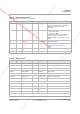
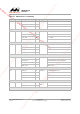
Table 5: USB 2.0 OTG Interface
1
NOTE: Available on 88-pin package only (88MW302)
88-Pin 68-Pin Pin Name Type Supply Description
61 -- USB_VBUS A, I/O USB_AVDD33 USB VBUS Selection Input In Device Mode
Unused in host mode; I/O for OTG mode to
supply +5V@10mA during session
negotiation.
GPIO_27 -- USB_DRV_VBUS A, O VDDIO_3 Drive 5V on VBUS
0 = do not drive VBUS
1 = drive 5V on VBUS
The USB_DRV_VBUS port is connected to
the SoC pad to drive an external power
management chip to provide power for USB
VBUS.
62 -- USB_ID A, I USB_AVDD33 USB 2.0 OTG IDPIN
63 -- USB_AVDD33 A, I -- USB 3.3V Analog Power Supply
See Table 16, Power and Ground, on
page 66.
64 -- USB_DP A, I/O USB_AVDD33 USB 2.0 Bus Data+
65 -- USB_DM A, I/O USB_AVDD33 USB 2.0 Bus Data–
1. After POR, if USB is in host mode, USB_DPUSB_DM will be SE0. If USB is in device mode, USB_DP/USB_DM will be High-z.
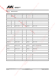
Table 6: UART Interface
1
88-Pin 68-Pin Signal Name Type Supply Description
GPIO_0 UART0_CTSn I VDDIO_0 UART 0 CTSn (active low)
GPIO_1 UART0_RTSn O VDDIO_0 UART 0 RTSn (active low)
GPIO_2 UART0_TXD O VDDIO_0 UART 0 TXD
GPIO_3 UART0_RXD I VDDIO_0 UART 0 RXD
GPIO_23 UART0_CTSn I VDDIO_AON UART 0 CTSn (active low)
GPIO_24 UART0_RXD I VDDIO_AON UART 0 RXD
GPIO_30 UART0_CTSn I VDDIO_2 UART 0 CTSn (active low)
GPIO_31 UART0_RTSn O VDDIO_2 UART 0 RTSn (active low)
GPIO_32 UART0_TXD O VDDIO_2 UART 0 TXD
GPIO_33 UART0_RXD I VDDIO_2 UART 0 RXD