
Data Sheet

GTI-ATM2022-X-datasheet page 18 of 25
18 / 25
17. PMU configuration
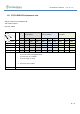
There is a PMU (Power Management Unit) inside the SoC ship, below is the description of these power rails.
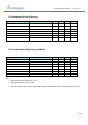
Power rail Pin on module Input/Output description
VBAT 6 I Battery or External Power Supply (DC 1.1 to 3.3V)
VDDIO 19 I Power input for digital and analog I/O
VDDIOP 10 O 1.8V IO power output generated by PMU
VAUX 12 O The auxiliary power output of typical 3.2V used internally by the PMU
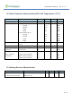
The PMU must be configured correctly to ensure correct operation. The following rules must be followed.
1. Use external VDDIO power supply
(One external power supply or battery with external IO supply)
VBAT to external power or battery
Connect VBAT to VDDIO
Connect VAUX to VDDIOP
Disable IO supply generation (
Note #2
)
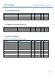
2. Use the internal VDDIO power supply
(one external power supply or battery with internally generated IO supply)
This is for the application that can use an internal 1.8V IO supply for better power consumption or
VBAT<=1.8V
VBAT to external power or battery
Connect VDDIOP to VDDIO
Note #2: Internal I/O supply VDDIOP can be disabled in firmware by controlling the register opt_disable_vddio, and it will not
be discussed here. The internal I/O supply is enabled by default.