
Data Sheet

GTI-ATM2022-X-datasheet page 14 of 25
14 / 25
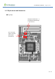
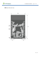
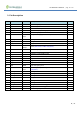
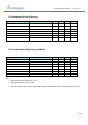
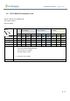
9. Pin Description
Pin Pin name I/O Description GPIO
1 GND PWR Power and signal ground
2 BT_RF RF 2.4 GHz Single-ended RF I/O for Bluetooth radio
3 WURX RF Wake receiver RF input, connect to ext. antenna
4 PWD I/O Power Down Input (Active High)
5 GND PWR Power and signal ground
6 VBAT PWR
Input
Battery Power Supply (DC 1.1 to 3.3V)
7 UART0_CTS I/O UART0_CTS P11
8 SPI_CS I/O SPIC_S P10
9 I2C0_SCL I/O I2C0_SCL P9
10 VDDIOP PWR
Output
1.8 V I/O power supply generated by SoC, connect to VAUX if
unused (See section 17 PMU configuration )
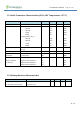
11 GND PWR Power and signal ground
12 VAUX PWR Reserved for switching regulator internal use
13 32K_OUT A
32.768 kHz crystal oscillator output
14 32K_IN A
32.768 kHz crystal oscillator input
15 SPI_MISO I/O SPI_MISO P13
16 SPI_CLK I/O SPI_CLK P20
17 SPI_MOSI I/O SPI_MOSI P22
18 GND PWR Power and signal ground
19 VDDIO PWR
Input
Power supply Input for digital I/O (See section 17 PMU
configuration )
20 UART0_RTS I/O UART0_RTS P24
21 UART0_TX I/O UART0_TX P23
22 UART0_RX I/O UART0_RX P25
23 I2C0_SDA I/O I2C0_SDA P30
24 P32 I/O UART1_RX P32
25 UART1_TX I/O UART1_TX P33
26 SWD_CLK I/O SWD_CLK -Serial Wire Debugger P1
27 SWD_IO I/O SWD_IO-Serial Wire Debugger P2
28 GND PWR Power and signal ground