
Static Report


Büro für Tragwerksplanung und Ingenieurbau
vom Felde + Keppler GmbH & Co. KG
11
Lütticher Straße 10
-
12
52064 Aachen
Telefon
:
0241 / 70 96 96
Telefax: 0241 / 70 96 46
b u e r o @ v o m - fe l d e . de
Interaktion Biegung und Normalkraft an der Kupplung
Interaction bending and normal force at coupler
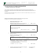
Normalkraft und Biegemomente werden über die Schweißnaht zwischen Kupplung und
Gurtrohr übertragen.
Normal force and bending moments are transmitted by the welding seam between coupler and chord.
Nachweis der Interaktion Biegung und Normalkraft an Kupplung
Verification of interaction bending and normal force at coupler
=> (Nsd
G
/ NRd
G
)
1,3
+ (Msd
G
/ MRd
G
)
< 1,0
mit Nsd
G
= Nsd / 4 + Msd / (2 · 0,08 m) n = 2 b = 0,08 m
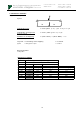
Berechnung des lokalen Biegemomentes im Gurtrohr:
Calculation of the local bending moment im Gurtrohr:
Der Einfluss der ausmittigen Anordnung der Diagonalen (offset) wurde in Vergleichsrechnung
am Stabwerksmodell der Traversen untersucht. Der Nachweis am Obergurt ist maßgebend!
The influence oft the offset oft he bracing was determined by comparative calculations with a framework. The
verfification at the upper chord is relevant!
Widerstandswerte
Resistance values
NRd
G
= zulässige Beanspruchung des Gurtrohrs in der WEZ (siehe folgende Tabelle):
= allowable loading of the chord in the heat affected zone (see following table):
Gurtrohr im Bereich der WEZ an der Kupplung und an Kreuzungspunkten von Diagonalen
main chord in heat affected zone at coupler
N
Rd
=A x 0,8* x fu,haz / Y
M2
=
13,39 [kN]
*(WIG
TIG
)
örtliche Schweißnaht nach Kap. 6.2.9.3 (1)
local welding seam acc. chapter 6.2.9.3 (1)
MRd
G
= MuRd (siehe folgende Tabelle):
= MuRd (see following table):
Lokale Biegung Gurtrohr Knotenpunkt vollst. in WEZ
Local bending of chord
MuRd = Wnet · fu / yM2=
6,03
[kNcm] nach Gl. 6.24
acc. equation 6.24
Zusammenfasung Bemessungswerte für die Interaktion an der Kupplung:
Summary of design values fort he interaction at the coupler:
NRd
G
= 13,39 kN
MRd
G
= 6,03 kNcm
Msd
G
= 16,7 kNcm / 10 kN ⋅
⋅⋅
⋅ Qsd = 1,67 cm ⋅
⋅⋅
⋅ Qsd
Hinweis: Nsd, Msd und Qsd: globale Schnittgrößen in der Traverse (in kN bzw. kNm)
Note:
global internal forces in the truss (in kN resp. kNm)
Die globalen Schnittgrößen sind Bemessungsschnittgrößen, die die folgenden
Sicherheitsbeiwerte nach Eurocode enthalten:
The global internal forces include the following safety factors acc. Eurocode:
Eigengewicht der Traversen: yF = 1,35
selfweight of the truss:
Nutzlasten auf der Traversen: yF = 1,50
Net load on the truss