54Mbps Wireless Network ROUTER USER’S MANUAL Model Name: Version: Date: GL2454RT-QA0 1.
Contents 1. 2. 3. Overview................................................................................................................4 1.1 Product Feature ..........................................................................................4 1.2 System Requirements.................................................................................4 1.3 Applications ...............................................................................................4 Getting Start .......................
4. 3.5.5 Firewall Rule................................................................................42 3.6 Management.............................................................................................44 3.6.1 SNMP...........................................................................................44 3.6.2 Remote Management ...................................................................45 3.7 Tools.........................................................................................
1. Overview 1.1 Product Feature ● ● ● ● Compliance with IEEE 802.11g and 802.11b standards Highly efficient design mechanism to provide unbeatable performance Strong network security with WEP and 802.1X encryption Achieving data rate up to 54Mbps for 802.11g and 11Mps for 802.11b with wide range coverage; high performance to deliver up to 108Mbps raw data rate for 802.11g ● Quick and easy setup with Web-based management utility 1.
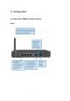
2. Getting Start 2.
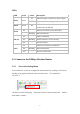
LEDs: LED Color Power Green Status On Indicates proper connection to power supply. OFF Green Status Description The unit is not receiving power Indicates that the device is connected to the WLAN. On On Indicates connection to the WAN port WAN Blinking On WLAN Link is established On Blinking Off — Packet transmit or receive activity No Link activity On LAN Data transmission. Indicates connection is established. On Blinking Off — Data transmissions No LAN connections 2.
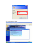
Now, the main menu screen is popup.
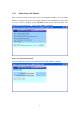
2.2.2 Quick Setup with Wizard Setup wizard is provided as the part of the web configuration utility. You can simply follow the step-by-step process to get your wireless router configuration ready to run in 6 easy steps by clicking on the “Wizard” button on the function menu. The following screen will appear. Please click “Next” to continue. Step 1: Set your new Password You can change the password as you like and then click “Next” to continue.
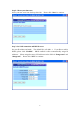
Step2: Choose your time zone Select your time zone from the drop down list. Please click “Next” to continue. Step 3: Set LAN connection and DHCP server Set your IP address and mask. The default IP is 192.168.1.1. If you like to enable DHCP, please click “Enabled”. DHCP enabled is able to automatically assign IP addresses. Please assign the range of IP addresses in the fields of “Range start” and “Range end”. Please click “Next” to continue.
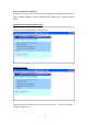
Step 4: Set Internet connection Select how the router will set up the Internet connection: Obtained IP automatically; Fixed IP address; PPPoE to obtain IP automatically; PPPoE with a fixed IP address; PPTP. Obtain IP automatically (DHCP client): If you have enabled DHCP server, choose "Obtain IP automatically (DHCP client)" to have the router assign IP addresses automatically. Fixed IP Address: If Fixed IP address is assigned, the below screen will pop up. Please set the WAN address and DNS server.
PPPoE to obtain IP automatically: 11
PPPoE with a fixed IP address: 12
PPTP: 13
Step 5: Set Wireless LAN connection Click “enable” to enable wireless LAN. If you enable the wireless LAN, type the SSID in the text box and select a communications channel. The SSID and channel must be the same as wireless devices attempting communication to the router. Step 6: Restart The Setup wizard is now completed. The new settings will be effective after the Wireless router restarted. Please click “Restart” to reboot the router.
3. Configuration 3.1 LAN Setting The screen enables you to configure the LAN & DHCP Server, set WAN parameters, create Administrator and User passwords, and set the local time, time zone, and dynamic DNS. 3.1.1 LAN & DHCP Server This page enables you to set LAN and DHCP properties, such as the host name, IP address, subnet mask, and domain name. LAN and DHCP profiles are listed in the DHCP table at the bottom of the screen. Host Name: Type the host name in the text box.
DHCP Server: Enables the DHCP server to allow the router to automatically assign IP addresses to devices connecting to the LAN. DHCP is enabled by default. All DHCP client computers are listed in the table at the bottom of the screen, providing the host name, IP address, and MAC address of the client. Start IP: Type an IP address to serve as the start of the IP range that DHCP will use to assign IP addresses to all LAN devices connected to the router.
subnet mask, and default gateway in the text boxes. Your ISP will provide you with this information. DNS 1/2/3: Type up to three DNS numbers in the text boxes. Your ISP will provide you with this information. MAC Address: If required by your ISP, type the MAC address of the router WAN interface in this field. DNS 1/2/3: Type up to three DNS numbers in the text boxes. Your ISP will provide you with this information. 3.1.3 Password This screen enables you to set administrative and user passwords.
3.1.4 Time This screen enables you to set the time and date for the router's real-time clock, select your time zone, and enable or disable daylight saving. Local Time: Displays the local time and date. Time Zone: Select your time zone from the drop-down list. Daylight Saving: Enables you to enable or disable daylight saving time. When enabled, select the start and end date for daylight saving time.
3.1.5 Dynamic DNS This allows the DDNS server what your current IP address is when you are on-line. You firstly need to register your preferred DNS on the DDNS providers. Then, please fill the related information in the below fields: DDNS server address, Host Name, User Name and Password.
3.2 Wireless This section enables you to set wireless communications parameters for the router's wireless LAN feature. 3.2.1 Basic This page allow you to enable and disable the wireless LAN function, create a SSID, and select the channel for wireless communications. Enable/Disable: Enables and disables wireless LAN via the router. SSID: Type an SSID in the text box. The SSID of any wireless device must match the SSID typed here in order for the wireless device to access the LAN and WAN via the router.
Open System allows public access to the router via wireless communications. Shared Key requires the user to set a WEP key to exchange data with other wireless clients that have the same WEP key. Mode: Select the level of encryption you want from the drop-down list. The router supports, 64- and 128-bit encryption. WEP Key: Select WEP Key - 64 or 128 bits from the drop-down list. Key 1 ~ Key 4: Enables you to create an encryption scheme for Wireless LAN transmissions.
If WPA is selected, please set the parameters for the RADIUS server. referred to the 802.1X setting.
3.2.3 Advanced This screen enables you to configure advanced wireless functions. Beacon Interval: Type the beacon interval in the text box. You can specify a value from 1 to 1000. The default beacon interval is 100. RTS Threshold: Type the RTS (Request-To-Send) threshold in the text box. This value stabilizes data flow. If data flow is irregular, choose values between 256 and 2432 until data flow is normalized. Fragmentation Threshold: Type the fragmentation threshold in the text box.
mode: Super G without turbo; Super G with Dynamic turbo and Super G with Static turbo. Turbo mode indicates the combination of two channels to enhance the throughput. Super G without turbo indicates that it is on Super G mode without the channel’s combination. Dynamic turbo is able to automatically detect if any ‘SuperG based’ product is available. If no, the connection is via ‘normal’ G.. Static turbo means it will not go back to ‘normal’ G once it starts. 3.2.4 802.
by the Radius server. 3. Enter the IP address of and the Port used by the Primary Radius Server Enter the Shared Secret, which is used by the Radius Server. 4. Enter the IP address of, Port and Shared Secret used by the Secondary Radius Server. (Click “Help” to get interpretation for Encryption Key and Radius Server.) 5. Click “Apply” button for the 802.1x settings to take effect after Wireless router reboots itself. Note: As soon as 802.
Firmware Version: Displays the latest build of the router firmware interface. After updating the firmware in Tools - Firmware, check this to ensure that your firmware was successfully updated. LAN: This field displays the router's LAN interface MAC address, IP address, subnet mask, and DHCP server status. Click DHCP Table to view a list of client stations currently connected to the router LAN interface.
Click Last Page to view the final page of the log Click Previous Page to view the page just before the current page Click Next Page to view the page just after the current page Click Clear Log to delete the contents of the log and begin a new log Click Refresh to renew log statistics Time: Displays the time and date that the log entry was created. Message: Displays summary information about the log entry. Source: Displays the source of the communication.
SMTP Server: Type the SMTP server address for the email that the log will be sent to in the next field. Send to: Type an email address for the log to be sent to. Click Email Log Now to immediately send the current log. Syslog Server: Type the IP address of the Syslog Server if you want the router to listen and receive incoming Syslog messages. Log Type: Enables you to select what items will be included in the log: ● System Activity: Displays information related to router operation.
Click Reset to erase all statistics and begin logging statistics again.
3.3.5 Wireless This screen enables you to view information about wireless devices that are connected to the wireless router. Connected Time: Displays how long the wireless device has been connected to the LAN via the router. MAC Address: Displays the devices wireless LAN interface MAC address.
3.4 Routing This selection enables you to set how the router forwards data: Static and Dynamic. Routing Table enables you to view the information created by the router that displays the network interconnection topology. 3.4.1 Static It enables you to set parameters by which the router forwards data to its destination if your network has a static IP address. Network Address: Type the static IP address your network uses to access the Internet.
page. Update: Select one of the entries in the static IP address table at the bottom of the page and, after changing parameters, click Update to confirm the changes. Delete: Select one of the entries in the static IP address table at the bottom of the page and click Delete to remove the entry. New: Click New to clear the text boxes and add required information to create a new entry. 3.4.2 Dynamic This screen enables you to set NAT parameters. NAT: Click the radio buttons to enable or disable NAT.
3.4.3 Routing Table This screen enables you to view the routing table for the router. The routing table is a database created by the router that displays the network interconnection topology. Network Address: Displays the network IP address of the connected node. Network Mask: Displays the network (subnet) mask of the connected node. Gateway Address: Displays the gateway address of the connected node. Interface: Displays whether the node is connected via a WAN or LAN.
3.5.1 Filters Using filters to deny or allow the users to access. Five types of filters to select: MAC, URL blocking, IP, Protocol filter and Domain blocking. MAC Filters: MAC Filter: Enables you to allow or deny Internet access to users within the LAN based upon the MAC address of their network interface. Click the radio button next to Disabled to disable the MAC filter. Disable: Once the function of MAC filter is disable, those listed in the MAC Table are allowed Internet access.
Add: Click to add the user to the list at the bottom of the page. Update: Click to update information for the user, if you have changed any of the fields. Delete: Select a user from the table at the bottom of the list and click Delete to remove the user profile. New: Click New to erase all fields and enter new information. URL Blocking: You could enable URL blocking to deny the users from accessing the specified URL. Add those specified URL in the text box.
IP Filters: This screen enables you to define a minimum and maximum IP address range filter; all IP addresses falling in the range are not allowed Internet access. The IP filter profiles are listed in the table at the bottom of the page. (Note: Click anywhere in the item. Once the line is selected, the fields automatically load the item's parameters, which you can edit.) Enable: Click to enable or disable the IP address filter. Range Start: Type the minimum address for the IP range.
Domain Blocking: You could specify the domains which allow users to access or deny by clicking one of the two items. Also, add the specified domains in the text box.
Protocol Filters: This screen enables you to allow and deny access based upon a communications protocol list you create. The protocol filter profiles are listed in the table at the bottom of the page. Note: When selecting items in the table at the bottom, click anywhere in the item.
3.5.2 Virtual Server This screen enables you to create a virtual server via the router. If the router is set as a virtual server, remote users requesting Web or FTP services through the WAN are directed to local servers in the LAN. The router redirects the request via the protocol and port numbers to the correct LAN server. The Virtual Sever profiles are listed in the table at the bottom of the page. Note: When selecting items in the table at the bottom, click anywhere in the item.
item and have made changes. Delete: Select a list item and click Delete to remove the item from the list. New: Click New to erase all fields and enter new information. 3.5.3 Special AP This screen enables you to specify special applications, such as games, that require multiple connections that are inhibited by NAT. The special applications profiles are listed in the table at the bottom of the page. Note: When selecting items in the table at the bottom, click anywhere in the item.
● Port Range: Type the port range that can be used to access the application in the text boxes. Incoming: Defines which incoming communications users are permitted to connect with. ● Protocol: Select the protocol (TCP, UDP, or ICMP) that can be used by the incoming communication. ● Port: Type the port number that can be used for the incoming communication. Add: Click to add the special application profile to the table at the bottom of the screen.
Enable: Click to enable or disable the DMZ. DMZ Host IP: Type a host IP address for the DMZ. The computer with this IP address acts as a DMZ host with unlimited Internet access. Apply: Click to save the settings. 3.5.5 Firewall Rule This screen enables you to set up the firewall. The router provides basic firewall functions, by filtering all the packets that enter the router using a set of rules. The rules are in an order sequence list--the lower the rule number, the higher the priority the rule has.
Destination: Defines the destination of the incoming packet that the rule is applied to. ● Interface: Select which interface (WAN or LAN) the rule is applied to. ● IP Range Start: Type the start IP address that the rule is applied to. ● IP Range End: Type the end IP address that the rule is applied to. ● Protocol: Select the protocol (TCP, UDP, or ICMP) of the destination. ● Port Range: Select the port range. Add: Click to add the rule profile to the table at the bottom of the screen.
3.6 Management Management enables you to set up SNMP and Remote Management feature. 3.6.1 SNMP This screen enables you to configure SNMP. Enabled/Disabled: Click to enable or disable SNMP. System Name: Displays the name given to the router. System Location: Displays the location of the router (normally, the DNS name). System Contact: Displays the contact information for the person responsible for the router. Community: SNMP system name for exchanging SNMP community messages.
3.6.2 Remote Management This screen enables you to set up remote management. Using remote management, the router can be configured through the WAN via a Web browser. A user name and password are required to perform remote management. HTTP: Enables you to set up HTTP access for remote management. ● Enable: Click to enable or disable HTTP access for remote management.
IDENT: Default is closed. This enables you to set port 113 stealth. 3.7 Tools This page enables you to restart the system, save and load different settings as profiles, restore factory default settings, run a setup wizard to configure router settings, upgrade the firmware, and ping remote IP addresses. 3.7.1 Restart Click Restart to restart the system in the event the system is not performing correctly.
3.7.2 Settings This screen enables you to save your settings as a profile and load profiles for different circumstances. You can also load the factory default settings, and run a setup wizard to configure the router and router interface. Save Settings: Click to save the current configuration as a profile that you can load when necessary. Load Settings: Click Browse and go to the location of a stored profile. Click Load to load the profile's settings.
3.7.3 Firmware This screen enables you to keep the router firmware up to date. Please follow the below instructions: 1. Download the latest firmware from the manufacturer's Web site, and save it to your disk. 2. Click Browse and go to the location of the downloaded firmware file.
3.7.4 Ping Test The ping test enables you to determine whether an IP address or host is present on the Internet. Type the host name or IP address in the text box and click Ping. 4. Glossary Access Point An interview networking device that seamlessly connects wired and wireless networks Authentication Authentication refers to the verification of a transmitted message’s integrity. DMZ DMZ (DeMilitarized Zone) is a part of a network that is located between a secure LAN and an insecure WAN.
addresses to client stations logging onto a TCP/IP network, which eliminates the need to manually assign permanent IP addresses. DNS DNS stands for Domain Name System. DNS converts machine names to the IP addresses that all machines on the net have. It translates from name to address and from address to name. Domain Name The domain name typically refers to an Internet site address.
Web server and transmits HTML pages to client browser (for example Windows IE). HTTP addresses all begin with the prefix 'http://' prefix (for example, http://www.yahoo.com). ICMP ICMP (Internet Control Message Protocol) is a TCP/IP protocol used to send error and control messages over the LAN (for example, it is used by the router to notify a message sender that the destination node is not available).
also provides a certain amount of security by acting as a firewall by keeping individual IP addresses hidden from the WAN. (Network) Administrator The network administrator is the person who manages the LAN within an organization. The administrator's job includes ensuring network security, keeping software, hardware, and firmware up-to-date, and keeping track of network activity. NTP NTP (Network Time Protocol) is used to synchronize the realtime clock in a computer.
between the source of a packet and its destination. RTS RTS (Request To Send) is a signal sent from the transmitting station to the receiving station requesting permission to transmit data. Server Servers are typically powerful and fast machines that store programs and data. The programs and data are shared by client machines (workstations) on the network. SMTP SMTP (Simple Mail Transfer Protocol) is the standard Internet e-mail protocol.
WAN WAN (Wide Area Network) is a communications network that covers a wide geographic area such as a country (contrasted with a LAN, which covers a small area such as a company building).
Federal Communication Commission Interference Statement This equipment has been tested and found to comply with the limits for a Class B digital device, pursuant to Part 15 of the FCC Rules. These limits are designed to provide reasonable protection against harmful interference in a residential installation. This equipment generates, uses and can radiate radio frequency energy and, if not installed and used in accordance with the instructions, may cause harmful interference to radio communications.