
Manual


9
f. Leave wires connected.
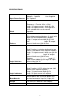
6. LATCH TEST
a. Jumper CLOCK X to PB1. Jumper CLOCK Y to
PB2. All LEDs should be lit.
b. Set switch "0" thru 3 to not OPEN. All LEDs
should be lit.Press and release PB1; "D0" thru
“D3” should go out.
c. Set switch 4 thru 7 to not OPEN. “D4”
through “D7” should still be lit.
Press and release PB2; “D4” through “D7” should go out.
Remove CLOCK jumpers.
7. INPUT PORT TEST
a. Jumper ENABLE X to PB1.
Jumper ENABLE Y to PB2. All
LEDs should be out.
b. Set all 8 switches to OPEN. All LEDs
should still be out.
Press and hold PB1: "D0"through “D3” should light.
Release PB1: "D0" through “D3” should go out.
Press and hold PB2: “D4” through “D7” should light.
Release PB2: “D4” through “D7” should go out.
8. Turn POWER switch OFF: Unit should not function.
CHECKOUT COMPLETE