4005 Sweep Function Generator with External Frequency Counter Instruction Manual Revision: 11/2010
Model 4005 5MHz Sweep/Function Generator Thank you for purchasing the Model 4005. For proper use of this precision instrument, please read this operation manual carefully. Note 1. To fully maintain the precision and reliability of the 4005, please use it within the range of its intended use (temperature 10 C~35 C, humidity 45%~85%) 2. Please allow a pre-heating period of 30 minutes before use. 3. This instrument should be used with a triple line power cord for safety. 4.
Safety Symbols 1. 2. Functional earth terminal on the rear panel. 3 4. 5. 6. 7.
CONTENTS 1. PRODUCT DESCRIPTION 1-1. Introduction ----------------------------------------------------------------- ( 1-2. Technical Specifications ------------------------------------------------- ( 1-3. Equipment Ratings -------------------------------------------------------- ( 1-4. Supplied Accessories ---------------------------------------------------- ( 6 6 8 8 ) ) ) ) 2. INSTALLATION 2-1. Initial Inspection ----------------------------------------------------------- ( 2-2.
1. Model 4005 PRODUCT DESCRIPTION 1-1. Introduction The 4005 is designed to be used as a FUNCTION GENERATOR, SWEEP GENERATOR, PULSE GENERATOR and a FREQUENCY COUNTER, offering a wide range of applications in both analog and digital electronics such as engineering, manufacturing, servicing, education and hobbyist fields. VCF (voltage controlled frequency) produces precision sine, square and triangle waves over the 0.05Hz to 5MHz for sub-audible, audio, ultrasonic and RF applications.
WAVEFORM CHARACTERISTICS Sine wave Square wave Triangle wave TTL Output CMOS Output DUTY RATIO -Flatness : ± 3dB to 5 MHz (more than 14Vpp) -Distortion : Less than 1% at 10 Hz to 100 KHz -Rise and Fall Time : Less than 25 nS (at 5MHz) -Linearity : More than 99% at 0.5 Hz to 100 KHz -Rise and Fall Time : Less than 30 nS (at 1MHz) -Output Level : TTL Level (H 2.4V, L 0.
1-3. Equipment Ratings Plug and Socket : 3 wire AC power plug and 3 wire outlet Power & Fuse Ratings Input Voltage Fuse Power Max. 103 126V AC (50/60Hz) F 0.5A / 250V 206 252V AC (50/60Hz) F 0.2A / 250V 15 W Operating Environment TEMPERATURE : 0 °C to + 40 °C (Accuracy Specified at 23°C ± 5 °C) HUMIDITY : up to 85% to 40°C without temperature extremes which may cause condensation within the instrument.
2. INSTALLATION 2-1. Initial Inspection This instrument was carefully inspected both mechanically and electrically before shipment. It should be physically free of damage. To confirm this, the instrument should be inspected for physical damage in transit. Also, check that supplied accessories are present and correct. 2-2. Connecting AC Power This instrument requires 115V AC or 230V AC (50-60 Hz) power socket with protective earth contact (PE-contact).
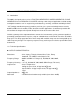
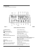
3. OPERATION 3-1. Controls, Indicators and Connectors Figure 1. FRONT PANEL OPERATOR’S CONTROLS POWER SWITCH: Push for Power On/Off RANGE SWITCHES: Frequency Range Selector FUNCTION SWITCHES: Select Sine wave, Triangle Wave or Square Wave Output ATTENUATOR: Selects Output Level by -20 dB. INTERNAL/EXTERNAL SWITCH: IN: for External Frequency Counter LOW PASS FILTER: DISPLAY: GATE TIME INDICATOR: OUT: for Internal Frequency Counter.
FINE FREQUENCY DIAL: Controls output fine frequency in the selected range. SWEEP RATE CONTROL: On-Off Switch for the Internal Sweep Generator. Adjusts Sweep Rate of the Internal Sweep Generator. SWEEP WIDTH CONTROL: SYMMETRY CONTROL: Pull out to adjust the Sweep Magnitude Adjust Symmetry of Output Waveform 1:1 to 10:1 with Push/Pull Switch On. Selects TTL or CMOS Mode Out: for CMOS Level Control In: for TTL Level. Adds Positive or Negative DC Component to the Output Signal.
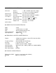
Figure 2.
3-2. Operating Instructions This instrument is capable of generating a wide variety of waveforms, as well as the ability of counting an external frequency with high resolution of 6 digits. All of its benefits and features can be mastered by thoroughy understanding the operating procedures outlined in this manual. One of the best ways to initially gain this familiarization is to connect the generator to an oscilloscope. Observe the waveforms and notice the effects of the various controls on the waveforms.
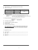
TTL Pulse 0V Triangle 0V Sine 0V Square 0V Figure 3 OUTPUT WAVEFORMS AND PHASE RELATIONSHIPS I. A positive or negative DC component can be added to the signal at the 50 BNC by use of the DC OFFSET control, as required by the circuit into which the signal is being injected. J. A fixed amplitude TTL square wave is available at the TTL OUT BNC on the front panel. This signal is unaffected by the AMPLITUDE, ATTENUATOR or DC OFFSET.
C. It is easier to accurately set the FREQ. dial if settings between 0.1 and 5.0 are used. Since the dial rotation overlaps ranges, it is not usually necessary to use readings below 1. If this occurs, change to a lower range and use a higher dial setting. +5V A . Z e ro D C O ffs e t w ith m a x im u m s ig n a l 0V -5 V +5V B .
3-4. Use as a Pulse Generator In a symmetrical square wave, sine wave, or triangle wave, the positive and negative transitions are of equal time duration, or 1:1 ratio. This condition is present when the SYMMETRY control is off. When the SYMMETRY control is pulled and rotated, the positive transition can be stretched in relation to the negative transition, up to at least, 10:1 ratio.
b. Adjust the longer duration portion of the waveform (rest time for pulses, rise time for ramp waves) with the SYMMETRY control. D. If a specific pulse width (specific fall time for ramp wave) is not critical, but a specific repetition rate is required, the desired waveform may be obtained as follows: a. Observe the oscilloscope and adjust the SYMMETRY control to obtain the approximate desired pulse width vs. rest time ratio (rise time vs. fall time ratio for ramp waves). b.
3-5. TTL/CMOS OUTPUT TTL/CMOS output is specifically designed for compatibility with TTL/CMOS digital logic circuits. Setup time is considerably reduced because the fixed logic levels and polarity are ready for direct injection into TTL/CMOS circuits. There is a need for protection from the accidental application of too high an amplitude or incorrect DC offset which might damage semiconductors. Another advantage is the extremely fast rise time and fall time of signal.
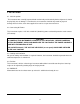
RANGE HIGHEST FREQ. OBTAINABLE(Hz) FREQ. DEVIATION FOR EACH 0.1 VOLT VCF IN CHANGE(Hz) 5 50 500 5K 50K 500K 5M 5 50 500 5K 50K 500K 5M 0.05 0.5 5 50 500 5K 50K Frequency Deviation vs VCF IN Voltage. B. For an example, it is assumed that we wish to generate a 455 KHz signal with FM deviation of ±15 KHz (30 KHz swing). The 500k range will be used to obtain the 455 KHz carrier with the FREQ. dial set to 4.55. The highest frequency obtainable in this range is 500kHz. One percent of 500kHz is 5 KHz.
B. This voltage is first established by the setting of the FREQ dial. Any voltage input drives the VCF to a HIGHER FREQUENCY. However, the VCF can never be driven beyond its range limits (the highest and lowest frequencies that can be attained with the dial on a given range.) B. With the FREQ dial set at its minimum ( 0.05) and 0 volts at the VCF in BNC, the generator’s output frequency is at the lower limit of the selected range.
Additional information on programmed frequency selection is given in the “APPLICATIONS” chapter of this manual. 3-9. Use as a Sweep Generator 1) Procedure A. Set up the Model 4005 for function generator operation. B. Select the highest frequency to be swept with the RANGE switch and the lowest frequency to be swept with the FREQ. dial. C. Adjust amount of sweep with the sweep rate control. D. Adjust repetition rate of sweep with the sweep rate control.
F. LOW-PASS FILTER: If necessary, engage the LPF (low pass filter) switch. This will route the input through a low pass filter (-3 dB point of approximately 100 KHz) prior to passing through to the frequency counter. This helps eliminate counting errors in low frequency measurements by minimizing effects of high frequency noise present on the input. CAUTION 1. APPLICATION OF INPUT VOLTAGES HIGHER THAN THE LIMITS LISTED IN THE SPECIFICATIONS SECTION MAY DAMAGE THE COUNTER.
4. MAINTENANCE CAUTION IT IS ESSENTIAL FOR SAFETY TO PROPERLY MAINTAIN AND SERVICE THIS INSTRUMENT WARNING VOLTAGES WITHIN THIS INSTRUMENT ARE SUFFICIENTLY HIGH AND MAY BE LIFETHREATENING. COVERS MUST NOT BE REMOVED EXCEPT BY PERSONS QUALIFIED AND AUTHORIZED TO DO SO. EXTREME CAUTION MUST BE OBSERVED ONCE THE COVERS HAVE BEEN REMOVED. 4-1. Fuse replacement Disconnect and remove all connections from any live power source. Unscrew fuse holder with a screw driver.
This marking shown on the product or literature indicates that it should The product should not be disposed with other household wastes. To prevent possible harm to the environment or human health from uncontrolled waste disposal, please separate this from other types of wastes and recycle it responsibly.
Limited One-Year Warranty Global Specialties, LLC warrants to the original purchaser that this product and its component parts will be free from defects in workmanship and materials for a period of one year from the date of purchase. Global Specialties, LLC will without charge, repair or replace, at its’ option, defective product or component parts. Returned product must be accompanied by proof of the purchase date in the form a sales receipt.
Model Number: ______________ Date Purchased:__________ Service Information Prior to sending any unit in for warranty, or non-warranty repair, the user must obtain a Return Merchandise Authorization (RMA) number from the factory. Please use the contact information below for the most convenient method of contact. After receipt of the RMA, return all merchandise to Global Specialties, LLC with pre-paid shipping.
22820 Savi Ranch Parkway Yorba Linda, CA 92887 USA TEL: 800-872-1028 FAX: 714-921-6422 www.globalspecialties.