Test Equipment Users Manual Model 3600 32 Channel Logic Analyzer Innovative Training Solutions www.globalspecialties.com Model 3600 User Manual_B.
June 2010 © 2010 Global Specialties All rights reserved. Specifications are subject to change without notice. All product names are trademarks of their respective companies. Model 3600 User Manual_B.
Table of Contents Model 3600 Introduction ������������������������������������������������������������������������������������� 1 Product Contents.................................................................................. 1 Operating Conditions........................................................................... 1 Safety Summary....................................................................................
Table of Contents Model 3600 Channel Label Setting.....................................................................9 Channel Color Setting........................................................................... 9 Channel Switch Setting......................................................................... 9 Threshold Setting............................................................................9 Sampled Signals............................................................................
Table of Contents Model 3600 Trigger Setting...............................................................................20 Signal Input......................................................................................... 21 Start Conditions.................................................................................. 21 Start Select........................................................................................... 21 Trigger Conditions....................................................
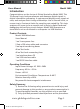
Users Manual Introduction Model 3600 Congratulations on the choice of Global Specialties Model 3600. This 32 channel Logic Analyzer observes and measures digital signals in digital information processing. It captures and displays many signals at once, and analyzes their timing relationships. Use its internal clock, or connect up to 2 external clocks for sampling rate variability. This logic analyzer will prove to be a versatile tool to help in digital hardware debugging and verifying circuit designs.
Users Manual Model 3600 3) Use Proper Power Cord. Use only the power cord specified for this product and certified for the country of use. 4) Ground the Product. This product is grounded through the grounding conductor of the power cord. To avoid electric shock, the grounding conductor must be connected to earth ground. Before making connections to the input or output terminals of the product, ensure that the product is properly grounded. 5) Observe All Terminal Ratings.
Users Manual Model 3600 stored in high-speed memory according to appointed addresses. Selecting the internal clock timing sampling will set the cycle of the sampling clock. State sampling with the external clock will select the phase of the sampling clock. During the sampling storage period, a “sequence add 1 counter ” supplies the storage address for the high-speed memory in the memory control circuit, each sampling clock makes the memory change to a new writing address.
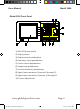
Users Manual Model 3600 Model 3600 Front Panel MODEL 3600 LOGIC ANALYZER FUNCTI ON V W X Y Z Syst em Tr i gger Si ngl e Channel Thr eshol d Q R S T U Ti me/ St at e Sour ce Save Recal l Run/ St op Di spl ay M ? ? 7 ? Fi nd N 8 O J K 5 6 E F G 2 P 3 L H ∩ A B C D 0 x Language Shi f t CLK2 CH31- CH16 Reset ADJUST 9 I 4 1 Zoom DATA ENTRY 1 Cur sor 2 Cur sor CLK1 CH15- CH0 1))ON / Off power switch 2))Display screen 3))Display control pushbuttons 4)
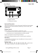
Users Manual Model 3600 Model 3600 Back Panel REPLACE FUSE AS SPECIFIED DISCONNECT POWER CORD BEFORE REPLACING FUSE AC 100-240V 1A USB RS-232 1)AC power source outlet 2)RS232 interface 3)USB device interface Keyboard Description There are 34 pushbuttons on the front panel divided into these groups: Display Control, Function Selection, Data Entry, Cursor Control, and Sample Rates. Display Control Display: display timing waveforms or data lists in cycle.
Users Manual Model 3600 Input Control 【↑】【↓】: select the setting parameters up to down in cycle 【←】: backspace, to delete the input data when the input hasn’t finished 【Shift】: used for inputting the English letters above the button 【Language】: English only Cursor Control and Adjust knob 【Cursor 1】: use the knob to move the cursor1 left and right 【Cursor 2】: use the knob to move the cursor2 left and right Sample Rates Run/Stop: circular run/stop recycling sample Single: single sample Reset: initialize t
Users Manual Model 3600 Waveform Interface Display The Waveform Interface displays 8 channels of timing waveforms, the serial number and the name of the waveform and includes four different vertical cursor lines in varied colors. There is one scale on the top of the waveform frame, and another one is on the bottom of the waveform frame. These are the zoom scales. The time value of every scale varies with the zoom coefficient.
Users Manual Model 3600 default parameter settings. Next the timing waveforms of internal code will be displayed. Most of functions performed by the logic analyzer are single or noncyclical signals included in high speed data streams. The analyzer can’t display the signals in real-time on the screen as an oscilloscope would, but it can sample the signals according to certain time rate (sample clock). The analyzer will catch and save any signal anomalies by setting up the appropriate trigger process.
Users Manual Model 3600 Channel Setting Channel Order Setting The double digit numbers 00-31 on the left side of the waveform display frame are the serial numbers for each channel. Press【Channel】 key to select the channel serial number setting. Then set the channel sequence using the numeric keys. The settings only change the position of channel waveforms on the screen so that different channels of waveforms can be closely displayed and easily compared.
Users Manual Model 3600 be used). The voltage will increase by turning the knob to right and decrease by turning the knob to left. When the voltage value passes the zero, the polarity sign will automatically change. The internal code-generator doesn’t pass the voltage comparator, so the settings on threshold voltage aren’t valid when sampling the internal code. The analyzer has 32 external signal input channels and 2 external clock channels.
Users Manual Model 3600 in the total line and address line. The amplitude characteristic of one group is identical and should also use the same comparison threshold voltage. However the instrument has 32 signal input channels and again, it is not necessary to setup 32 independently adjustable threshold voltages. But in practice, there are measured signals with different amplitudes for instance TTL, CMOS, and ECL. In many experimental circuits, the amplitudes required may vary.
Users Manual Model 3600 If there is a need to compare the waveforms, the method of channel order setting (see Channel Order Setting) can be used to display the desired waveforms. Waveform Rolling Left/Right The Model 3600 allows for 260,000 memory addresses for each channel, however only 280 data points can be viewed due to the horizontal width of the screen.
Users Manual Model 3600 Waveform Zoom In digital systems, changing rates of different logic levels can vary within different data channels. When trying to view these on the display, it is possible to have 8 channels with big differences in the changing rates of logic levels. This can cause viewing problems due to the large number of pulse waveforms crowded together on the screen and the fast changing logic level rates will not be seen clearly.
Users Manual Model 3600 gradually to minimize distortion. If distortion is found, the user should no longer continue compressing the waveform. Data Lookup - Search Function Model 3600 has a convenient search function. After a sampling of data, the user can find the data conforming to the setting conditions within a large group of sampled data. Parameters in the third row on the right bottom of the wave frame is the find-data which is a 32 bit data word in Hex format.
Users Manual Model 3600 are the same as timing waveform display mentioned in the Timing Waveform Display section. The functions of window addresses, rolling steps, find-data words are also identical. The difference is that rolling up and down in the data listing display equals rolling left and right in the timing waveform display. The found data is a row of orange data displayed in the upper part of data listing. The data listing cannot roll left and right, or zoom.
Users Manual Model 3600 This is done by reading the data value of the cursor without moving waveforms up and down to view. When turning the knob to make the measurement cursor move, the cursor parameter’s address value and data value will change dynamically with it. When the two cursors move into the same point, their parameter values are identical. The difference in value between cursor1 and cursor2 displays in the 4th row on the left bottom of the waveform frame.
Users Manual Model 3600 value difference between the two points. After finishing this type of measurement , press【cursor 2】key to recall it into display window and begin the next measurement. Data Listing Cursor In the Data Listing interface, cursor1, cursor2 and cursor measurement are the same as the cursors in the Timing Waveform interface.
Users Manual Model 3600 user takes samples using the inner clock to inner code generator, this also belongs to “synchronous sampling.” If state sampling is used as the sampling clock signal in a measured system, it is required to connect to special input channel clk1 or clk2. Otherwise the sampling will not start. If the noise in the external clock signal is too large, adjust the threshold voltage settings of the external clock to obtain a pure clock signal.
Users Manual Model 3600 desired signals and saves memory space. Sampling Cycle The logic analyzer captures data on the hop edge of the sampling clock and the data between two hop edges is ignored. (hop edge means the moment of potential shifting). If a longer sampling cycle is chosen, the fast-changing sections of the input signals will be missed. This causes the displayed waveforms to have distortion compared to the true waveforms of the input signals both in amplitude and time.
Users Manual Model 3600 Model 3600 sets sampling phase choices of rising edge sampling and falling edge samplingWhen connecting the timing sampling to an external signal with the internal clock, the sampling phase setting may be out of phase due to “asynchronous sampling”. Press【system】to select sample-phase and set sampling phase in numbers, press【0】to select clock falling edge, press【1】to select rising edge.
Users Manual Model 3600 Press【trigger】to display the graphical trigger setting interface. This will allow the user to view the entire sampling process directly, as well as the master trigger setting. Signal Input The signal input process is on the left of the trigger setting display. The externally tested signal from the probe passes through test hooks, “commuting case”, transmitting cable, connector, to “comparator”, then compared with the “threshold voltage” to generate digital signals.
Users Manual Model 3600 switch, the key【1】connects the switch. If the start select switch is connected, “the start conditions” will be short-circuited eliminating their use. For example, after pressing【Single】, the sampling process starts directly without detecting the start conditions, equal to random sample manually. The default setting of the “start select switch” is “connect” in order to make random sampling without specific sampling purpose and not needing to set the start conditions.
Users Manual Model 3600 Different from the start conditions, the trigger conditions sets three trigger limit switches, <, =,>. These are useful for testing the data with respect to the tested signals. The trigger limit switch can be set with number keys. Press the 【1】key to connect the switch, which connects only one in the three trigger limit switch. Once one switch is connected, the other two switches are disconnected. The default setting of the trigger limit switch is “=” connection.
Users Manual Model 3600 Store Delay The sampling process can stop automatically after the trigger process finishes. But in some applications, we want to delay a period of storage time of the sampling data in order to analyze some signals characteristics after trigger events.
Users Manual Model 3600 The 8 numbers on the right of the parameter are the values in Hex of the data the cursor indicates. For example: the sampled data of the 32 input channels, every number represents four channels. The data from left to right represents the 32 channels of waveforms from the top to the bottom in turn. Press【single】repeatedly for sampling and cursor indication. Because it is random sampling, the position of the trigger cursor line changes every time.
Users Manual Model 3600 the current displayed window as the start address. Cancel Storage If the user presses the【save】key in error and does not want to save the currently set parameter or waveforms, press【2】key to cancel. The original parameters or waveform will be maintained. Recall Press【Recall】to recall the saved parameters and waveform data. After recalling, they can be displayed with window and data list. The user can also measure and analyze them in different ways.
Users Manual Model 3600 Specifications Input Threshold voltage 32 data sample channels, two external clock channels 6 independently adjustable threshold voltages Adjusting range Input impedance - 6 V to + 6 V, Resolution: 0.
Users Manual Model 3600 Trigger Start conditions 32bits start-select, 32bits start-compare word Start select Trigger Limit Select-switch: On/Off 32 bits trigger select, 32 bits trigger comparing word select switch : >, =, < Event counter 1 to 999 times Trigger select Select switch: On/Off Store delay 1 to 256K sample cycles Trigger conditions Display Screen display Display format Waves rolling 5.
Users Manual Search cursor Model 3600 The sample point accords with the search conditions.
Users Manual Model 3600 Service Warranty Global Specialties warrants to the original purchaser that its products and the component parts thereof, will be free from defects in workmanship and materials for a period of one year from date of purchase. Global Specialties will, without charge, repair or replace, at its option, defective product or component parts. Returned product must be accompanied by proof of the purchase date in the form of a sales receipt. To obtain warranty coverage in the U.S.A.
Users Manual Model 3600 Customers not on open account must include payment in the form of a money order or credit card. For the most current repair charges please visit www.globalspecialties.com and click on Calibration & Repair. Return all merchandise to Global Specialties with pre-paid shipping. The flat-rate repair charge for Non-Warranty Service does not include return shipping. Return shipping to locations in North American is included for Warranty Service.
Innovative Training Solutions Global Specialties 22820 Savi Ranch Parkway Yorba Linda, CA 92887 1-800-572-1028 www.globalspecialties.com Model 3600 User Manual_B.