
User guide

4.7 REMOTE SENSE :
Remote sensing is accomplished by connecting the load
to remote sensing terminals on the front panel and
selecting the remote mode by pressing the "SENSE
MODE" push switch. The leads from the sensing
(+S and -S) terminals to the load will carry much less
current than the load leads and it is not required that these
leads be heavy as the load leads. However they must be
twisted or shielded to minimize noise pickup.
For reasonable load lengths remote sensing greatly
improves the performance of the supply. However, if
the load is located at a considerable distance from the
supply, added precautions must be observed to obtain
satisfactory operation. Notice that the voltage drop in the
leads subtracts directly from the available output voltage
and also reduces the amplitude of the feedback error
signals that are developed within the unit. Because of
these factors it is recommended that the drop in each
load lead does not exceed 0.5V.
7
SECTION 5
PART LIST & SCHEMATICS
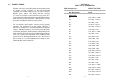
PCB Components ZSDT-CT/05 PCB
=======================================================================
Ref Designator Value
=======================================================================
RESISTORS
R1 270E, 2W, 5%, MOR
R2 47E, MFR, 1/4W, 5%
R3 10K, MFR, 1/4W
R4* 1K, MFR, 1/4W, 5%
R5 10E, MFR, 1/4W, 5%
R6 3.9K, MFR, 1/4W
R7 3.3K, 2W, 5%, MOR
R8 10K, MFR, 1/4W
R9 8.2K, MFR, 1/4W
R10 100K, MFR, 1/4W
R11 4.7E, MFR, 1/4W.
R12 1.5K, MFR, 1/4W.
R13 180K, MFR, 1/4W.
R14 390E, MFR, 1/4W.
R15 6.8K, MFR, 1/4W, 5%
R16 12K, MFR, 1/4W, 5%
R17 3.9K, MFR, 1/4W, 5%
R18 10K, MFR, 1/4W
R19 10K, MFR, 1/4W
R20 10K, MFR, 1/4W
R21 3.3K, 2W, 5%, MOR
R22 270E, 2W, 5%, MOR
R23# 82K, MFR, 1/4W, 5%
R24 4.7K, MFR, 1/4W, 5%
R25 24E, MFR, 1/4W, 5%
8