
User guide

SECTION - 4
OPERATING INSTRUCTIONS
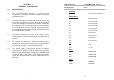
4.1 ACCEPTANCE TEST :
These acceptance tests ensure that the unit is in working
order after shipping. These tests may also be used to
verify basic operation when the unit has been restored
to normal use after prolonged storage.
4.2 VARIABLE OUTPUT SECTIONS
4.2.1 CONSTANT VOLTAGE MODE :
a) Ensure that the AC power switch is in the OFF position.
b) Connect the unit to a rated power source.
c) Turn the voltage and current controls fully counter
clockwise.
d) Connect a digital voltmeter (DVM) to the output
terminals, observing correct polarirty. The DVM must be
rated better than 0.5% accuracy.
e) Turn the power switch ON. The front panel digital meters
will light up and voltmeter and ammmeter displays will
read zero.
f) Turn the current control a 1/2 turn clockwise. Slowly turn
the voltage control clockwise and observe both the front
panel voltmeter and the DVM.
g) Compare the DVM reading with the front panel
voltmeter reading. The control range will be from 0 to
32V. The green voltage mode LED will be illuminated to
indicate CV mode of operation.
4.2.2 CONSTANT CURRENT MODE :
a) Ensure that the AC power switch is in the OFF position.
b) Connect the unit to a rated power source.
4
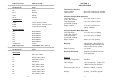
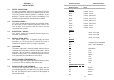
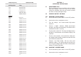
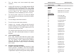
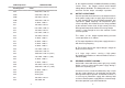
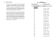
PCB Components ZSDT-CT/05 PCB
=======================================================================
Ref Designator Value
=======================================================================
C24 10µF/50V, ELE
C25 10µF/50V, ELE
C26 0.1µF/50V, CD
C27 470µF/50V, ELE
C29 1000µF/35V,ELE
DIODES
CR1 Not Used
CR2 1N4007, 1KV/1A
CR3 1N4007, 1KV/1A
CR4 1N4007, 1KV/1A
CR5 1N4007, 1KV/1A
CR6 1N4007, 1KV/1A
CR7 1N4007, 1KV/1A
CR8 1N4007, 1KV/1A
CR9 1N4007, 1KV/1A
C10 1N4007, 1KV/1A
CR11 1N4007, 1KV/1A
CR12 1N4007,1KV/1A.
CR13 1N4007,1KV/1A.
CR14 1N4007,1KV/1A
CR15 1N4007,1KV/1A
CR16 1N4007, 1KV/1A
CR17 1N4007, 1KV/1A
CR18 1N4007, 1KV/1A
CR19 1N4007, 1KV/1A
CR20 1N4007, 1KV/1A
CR21 1N4007, 1KV/1A
CR22 1N4007, 1KV/1A
11