
User Manual

User’s Manual
Attention & Warning
1. Use lift stacker on flat, hard surfaces.
2. Do not exceed maximum load capacity. Transport
goods according to load curve ensuring
load balance.
Operational Instructions
1. Lock wheel brakes and confirm height release valve
is closed.
2. Footstep pole adjusts fork pump height. To lower
forks, turn height release valve slowly until reaching
desired height.
3.
When the load exceeds 1.2 times of the load capacity
the safety will lock so that the forks cannot rise. This is
to ensure safe operation.
4. During transport, forks must be in the lowest
position for safety.
5. Descending speed may be adjusted by modifying
the positioning ring angle on the release valve pole.
6. WARNING! When raising fork, do not pump
footstep pole too quickly as this may cause cylinder
to deplete.
7. WARNING! When handling heavy loads, turn release
valve slowly for stability.
8. WARNING! When rising operation ceases, verify
release valve is securely closed for fork stability.
Daily Maintenance & Inspection
1. Inspect forklift prior to use. Do not operate if
damaged or in poor condition. Inspect all moving
parts for issue or noise.
2. Inspect hydraulic system for oil leakage.
3. Perform monthly inspection of forks, wheels, chains,
and more.
4.
Perform recommended lifting cylinder maintenance.
Replace hydraulic oil at 20 hours of run time and once
every 18 months or 300 hours whichever comes first.
Please fill in the specified hydraulic oil at the following
temperatures listed below:
When replacing oil, adjust pillar piston pole to
lowest position.
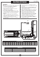
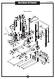
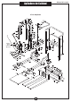
Installation
3
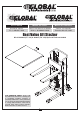
Best Value Lift Stacker
Required tools for assembly two 17mm wrenches
Part identification #11 fork assembly, #12 handrail
#13 cylinder assembly, #14 Chassis assembly, #15
Handrail guide and #16 connecting bolts; 4 sets.
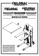
1. On an even surface, place the fork assembly #11 on
the chassis #14 as in the drawing.
2. Insert the handrail #12 through fork assembly #11
and Handrail guide # 15; until it meets with the
chassis #14., aligning the bottom hole of cylinder
pump with the chassis #14.
3. Remove the lower nut on both sides of the chain
assembly, being careful not to let the chain slip
through. Connect the upper portion of the chain to
the handrail #12 and then the lower portion to the
chassis #14. Tighten the bolts and using the cotter
pins supplied to secure.
4. The forklift height can be adjusted after installation
via the chain bolt.
5. Connect the handrail #12 and Chassis #14 using the
connecting bolts #16 supplied.
6. Make sure all parts are connected properly and
bolts are tight.
7. Make sure operation is steady without and with a
rated load.
Temperature Hydraulic Oil
23°F~ 113°F
L-HM68 hydraulic oil
(equivalent to ISOVG68)
5°F~ -41°F
L-HM46 hydraulic oil
(equivalent to ISOVG46)
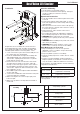
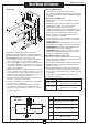
1 Out-pushing Cylinder
2 Turning Lifting and Falling Valve
3 Safety Valve
4 Oil Returning Valve
5 Work Valve
6 Work Cylinder
Hydraulic Principle
Drawing