
User's Manual
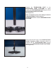


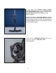

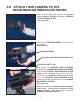


Figure 25
Rotate, and screw the CAMERA MOUNTING
PLATFORM into the THREADED INSERT in the top
of the CENTRAL POST.
(See Figure 25)
Figure 26
There are two ways to create this correct alignment.
The rst and easiest is to loosen the ADJUSTMENT
KNOB on the TELESCOPING CLAMP and rotate
the parts until correctly aligned, then simply re-tighten
the ADJUSTMENT KNOB.
(See Figure 26)
NOTE: Remember to leave at least one inch of
the TELESCOPING POST showing below the
TELESCOPING CLAMP.
16