
Installation Guide

INSTRUCTIONS D’INSTALLATION DES
PROFILÉS DE 32" (81,3 cm),
42" (106,7 cm) ET 48" (121,9 cm)
ET DES CAPUCHONS D’EXTRÉMITÉS
GEARTRACK
®
(Pour utilisation avec les produits Gladiator® Garageworks
uniquement)
W10343308D
Préparer les prolés GearTrack
®
IMPORTANT : Utiliser la longueur de vis adaptée au type de mur.
Voir le tableau ci-dessous.
Outillage et pièces
Rassembler les outils et pièces nécessaires avant de commencer
l’installation.
Lire et suivre les instructions fournies avec les outils indiqués ici.
Outillage et pièces nécessaires :
• Niveau • Localisateur de clou/vis (pour colombage)
• Mètre ruban • Détecteur de tension CA
• Perceuse • Équerre
• Scie • Crayon
• Vis (galvanisées ou résistantes aux intempéries) — pour montage
direct sur des poteaux de colombage
* Pour des poteaux de colombage de bois nu ou des murs garnis de panneaux,
utiliser une vis pour terrasse à tête fraisée résistant aux intempéries.
Pour un mur en parpaing ou en béton, utiliser une vis à maçonnerie à tête fraisée.
Pour un mur en panneaux de gypse dont l’épaisseur ne figure pas dans le tableau
ci-dessus, consulter l’illustration ci-dessous.
Prepare the GearTrack®Channels
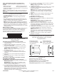
IMPORTANT:Use correct screw length for your wall type. See chart
below.
*For bare wood studs and covered walls, use an all-weather flat-head type deck screw.
For concrete block and poured masonry, use a flat-head type masonry screw.
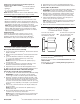
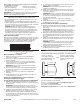
For drywall of a thickness not listed in the chart above, see graphic below.
A
B
C
D
E
A. Drywall
B. Wooden stud
C. Flat-head screw in
every slot at every stud
D. 1" (2.54 cm) min. to 1
1
⁄
4
" (3.18 cm)
max. if near wiring
E.
1
⁄
4
"
(0.635 cm)
Tools and Parts
Gather the required tools and parts before starting installation.
Read and follow the instructions provided with any tools listed here.
Tools and Parts Needed:
• Level
• Tape measure
• Drill
• Saw
• Screws (galvanized or all-weather)
Additional Tools and Parts Needed for
Masonry Block/Poured Concrete Wall Installation:
• Hammer drill
• Caulk gun
•
3
⁄ 16" x 1
3
⁄ 4" (4.45 cm) Flat-head masonry screws (6 screws per channel)
NOTE:GearTrack® Channels can be cut and drilled with ordinary
woodworking equipment. Additional tools may be needed.
Use Requirements
• Maximum coverage per wall is 33% of the wall surface area.
• Maximum weight limit is 75 lbs (34 kg) per linear ft (30.48 cm).
• GearTrack®Channels can be mounted directly to masonry wall, ov
er
drywall to wooden studs, or to bare wooden studs.
• Intended for use in a garage or basement.
NOTE:Before installing GearTrack® Channels to masonry walls, you
must waterproof the wall to avoid mildew or foundation damage.
Walls that appear dry may actually become damp when enclosed b
y
paneling. Install the channel in accordance with all local codes and
ordinances.
Channel Spacing
If channels are to be used to support accessory hooks and/or small
item bins, they may be spaced in any way desired. If channels are to
be
used to support Gladiator® Wall GearBoxes, they must be installed 18"
(46 cm) apart.
NOTE:Wall GearBox model (GAWGB000LG0) requires the channels to
be spaced 21" (53.34 cm) apart.
• Stud nder
• AC nder
• Square
• Pencil
• Construction adhesive
•
5
⁄ 32" Masonry drill bit
18" (46 cm)
W10343308B
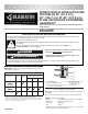
Screw Length for Wall Type
Screw
Length*
Masonry
Wall
Bare Wood
Studs
Drywall over Wood Studs
1
⁄2"
(1.27 cm)
5
⁄8"
(1.59 cm)
3
⁄4"
(1.91 cm)
#8 X 1
1
⁄4" (3.18 cm)
#8 X 2" (5.08 cm)
3
⁄16" X 1
3
⁄4" (4.45 cm)
(Screw Not Included)
32" (81.3 CM) AND 48" (121.9 CM)
AND 53.15" (135 CM)
GEARTRACK®CHANNEL
AND END CAP
INSTALLATION INSTRUCTIONS
(for use with Gladiator®GarageWorks products only)
(Screw Not Included)
A. Panneau de gypse
B. Poteau de colombage de bois
C. Vis à tête fraisée dans chaque rainure,
au niveau de chaque poteau
D. De 1" (2,54 cm) min. à 1¼"
(3,18 cm) max. si à
proximité d’un câble
E. ¼" (0,635 cm)
Prepare the GearTrack®Channels
IMPORTANT:Use correct screw length for your wall type. See chart
below.
*For bare wood studs and covered walls, use an all-weather flat-head type deck screw.
For concrete block and poured masonry, use a flat-head type masonry screw.
For drywall of a thickness not listed in the chart above, see graphic below.
A
B
C
D
E
A. Drywall
B. Wooden stud
C. Flat-head screw in
every slot at every stud
D. 1" (2.54 cm) min. to 1
1
⁄
4
" (3.18 cm)
max. if near wiring
E.
1
⁄
4
"
(0.635 cm)
Tools and Parts
Gather the required tools and parts before starting installation.
Read and follow the instructions provided with any tools listed here.
Tools and Parts Needed:
• Level
• Tape measure
• Drill
• Saw
• Screws (galvanized or all-weather)
Additional Tools and Parts Needed for
Masonry Block/Poured Concrete Wall Installation:
• Hammer drill
• Caulk gun
•
3
⁄ 16" x 1
3
⁄ 4" (4.45 cm) Flat-head masonry screws (6 screws per channel)
NOTE:GearTrack® Channels can be cut and drilled with ordinary
woodworking equipment. Additional tools may be needed.
Use Requirements
• Maximum coverage per wall is 33% of the wall surface area.
• Maximum weight limit is 75 lbs (34 kg) per linear ft (30.48 cm).
• GearTrack®Channels can be mounted directly to masonry wall, ov
er
drywall to wooden studs, or to bare wooden studs.
• Intended for use in a garage or basement.
NOTE:Before installing GearTrack® Channels to masonry walls, you
must waterproof the wall to avoid mildew or foundation damage.
Walls that appear dry may actually become damp when enclosed b
y
paneling. Install the channel in accordance with all local codes and
ordinances.
Channel Spacing
If channels are to be used to support accessory hooks and/or small
item bins, they may be spaced in any way desired. If channels are to
be
used to support Gladiator® Wall GearBoxes, they must be installed 18"
(46 cm) apart.
NOTE:Wall GearBox model (GAWGB000LG0) requires the channels to
be spaced 21" (53.34 cm) apart.
• Stud nder
• AC nder
• Square
• Pencil
• Construction adhesive
•
5
⁄ 32" Masonry drill bit
18" (46 cm)
W10343308B
Screw Length for Wall Type
Screw
Length*
Masonry
Wall
Bare Wood
Studs
Drywall over Wood Studs
1
⁄2"
(1.27 cm)
5
⁄8"
(1.59 cm)
3
⁄4"
(1.91 cm)
#8 X 1
1
⁄4" (3.18 cm)
#8 X 2" (5.08 cm)
3
⁄16" X 1
3
⁄4" (4.45 cm)
(Screw Not Included)
32" (81.3 CM) AND 48" (121.9 CM)
AND 53.15" (135 CM)
GEARTRACK®CHANNEL
AND END CAP
INSTALLATION INSTRUCTIONS
(for use with Gladiator®GarageWorks products only)
(Screw Not Included)
Longueur des vis en fonction du type de mur
Longueur
de vis*
Mur de
maçonnerie
Poteaux de
colombage
de bois nu
Panneaux de gypse sur poteaux
de colombage de bois
1
⁄
2
"
(1,27 cm)
5
⁄
8
"
(1,59 cm)
3
⁄
4
"
(1,91 cm)
n° 8 x 1
1
⁄
4
" (3,18 cm)
(vis non comprise)
✓
n° 8 x 2" (5,08 cm)
✓ ✓ ✓
3
⁄
16
" x 1
3
⁄
4
" (4,45 cm)
(vis non comprise)
✓
Prepare the GearTrack®Channels
IMPORTANT:Use correct screw length for your wall type. See chart
below.
*For bare wood studs and covered walls, use an all-weather flat-head type deck screw.
For concrete block and poured masonry, use a flat-head type masonry screw.
For drywall of a thickness not listed in the chart above, see graphic below.
A
B
C
D
E
A. Drywall
B. Wooden stud
C. Flat-head screw in
every slot at every stud
D. 1" (2.54 cm) min. to 1
1
⁄
4
" (3.18 cm)
max. if near wiring
E.
1
⁄
4
"
(0.635 cm)
Tools and Parts
Gather the required tools and parts before starting installation.
Read and follow the instructions provided with any tools listed here.
Tools and Parts Needed:
• Level
• Tape measure
• Drill
• Saw
• Screws (galvanized or all-weather)
Additional Tools and Parts Needed for
Masonry Block/Poured Concrete Wall Installation:
• Hammer drill
• Caulk gun
•
3
⁄ 16" x 1
3
⁄ 4" (4.45 cm) Flat-head masonry screws (6 screws per channel)
NOTE:GearTrack® Channels can be cut and drilled with ordinary
woodworking equipment. Additional tools may be needed.
Use Requirements
• Maximum coverage per wall is 33% of the wall surface area.
• Maximum weight limit is 75 lbs (34 kg) per linear ft (30.48 cm).
• GearTrack®Channels can be mounted directly to masonry wall, ov
er
drywall to wooden studs, or to bare wooden studs.
• Intended for use in a garage or basement.
NOTE:Before installing GearTrack® Channels to masonry walls, you
must waterproof the wall to avoid mildew or foundation damage.
Walls that appear dry may actually become damp when enclosed b
y
paneling. Install the channel in accordance with all local codes and
ordinances.
Channel Spacing
If channels are to be used to support accessory hooks and/or small
item bins, they may be spaced in any way desired. If channels are to
be
used to support Gladiator® Wall GearBoxes, they must be installed 18"
(46 cm) apart.
NOTE:Wall GearBox model (GAWGB000LG0) requires the channels to
be spaced 21" (53.34 cm) apart.
• Stud nder
• AC nder
• Square
• Pencil
• Construction adhesive
•
5
⁄ 32" Masonry drill bit
18" (46 cm)
W10343308B
Screw Length for Wall Type
Screw
Length*
Masonry
Wall
Bare Wood
Studs
Drywall over Wood Studs
1
⁄2"
(1.27 cm)
5
⁄8"
(1.59 cm)
3
⁄4"
(1.91 cm)
#8 X 1
1
⁄4" (3.18 cm)
#8 X 2" (5.08 cm)
3
⁄16" X 1
3
⁄4" (4.45 cm)
(Screw Not Included)
32" (81.3 CM) AND 48" (121.9 CM)
AND 53.15" (135 CM)
GEARTRACK®CHANNEL
AND END CAP
INSTALLATION INSTRUCTIONS
(for use with Gladiator®GarageWorks products only)
(Screw Not Included)
SÉCURITÉ
Risque possible de décès ou de blessure grave si vous ne
suivez pas immédiatement les instructions.
Risque possible de décès ou de blessure grave si vous
ne suivez pas les instructions.
Tous les messages de sécurité vous diront quel est le danger potentiel et vous disent comment réduire le risque de blessure et
ce qui peut se produire en cas de non-respect des instructions.
Votre sécurité et celle des autres est très importante.
Nous donnons de nombreux messages de sécurité importants dans ce manuel et sur votre appareil ménager. Assurez-vous de
toujours lire tous les messages de sécurité et de vous y conformer.
AVERTISSEMENT
DANGER
Voici le symbole d’alerte de sécurité.
Ce symbole d’alerte de sécurité vous signale les dangers potentiels de décès et de blessures graves à vous
et à d’autres.
Tous les messages de sécurité suivront le symbole d’alerte de sécurité et le mot “DANGER” ou
“AVERTISSEMENT”. Ces mots signifient :