
Installation Guide

INSTRUCCIONES DE INSTALACIÓN
PARA LOS CANALES DE 32" (81,3 cm),
42" (106,7 cm) Y 48" (121,9 cm) Y LAS
CUBIERTAS DE LOS EXTREMOS DE LA
MARCA GEARTRACK
®
(Para usar solamente con los productos Gladiator
®
GarageWorks)
W10343308D
Preparación de los canales
GearTrack
®
IMPORTANTE: Use el tornillo con el largo correcto para el tipo de
pared. Vea el cuadro a continuación.
Herramientas y piezas
Reúna todas las herramientas y piezas necesarias antes de
comenzar la instalación.
Lea y siga las instrucciones provistas con cualquiera de las
herramientas enlistadas aquí.
Piezas y herramientas necesarias:
• Nivel • Detector de vástagos
• Cinta para medir • Detector de corriente CA
• Taladro • Escuadra
• Sierra • Lápiz
• Tornillos (galvanizados o para todo clima); cuando se instale
directamente en vástagos de madera
* Para vástagos de madera sin recubrimiento y paredes recubiertas, use
un tornillo para todo clima de cabeza plana para cubierta.
Para bloques de concreto y albañilería vaciada, use un tornillo de albañilería
de cabeza plana.
Para placa de yeso de un espesor no indicado en la tabla de arriba, vea
la ilustración debajo.
Prepare the GearTrack®Channels
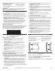
IMPORTANT:Use correct screw length for your wall type. See chart
below.
*For bare wood studs and covered walls, use an all-weather flat-head type deck screw.
For concrete block and poured masonry, use a flat-head type masonry screw.
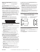
For drywall of a thickness not listed in the chart above, see graphic below.
A
B
C
D
E
A. Drywall
B. Wooden stud
C. Flat-head screw in
every slot at every stud
D. 1" (2.54 cm) min. to 1
1
⁄
4
" (3.18 cm)
max. if near wiring
E.
1
⁄
4
"
(0.635 cm)
Tools and Parts
Gather the required tools and parts before starting installation.
Read and follow the instructions provided with any tools listed here.
Tools and Parts Needed:
• Level
• Tape measure
• Drill
• Saw
• Screws (galvanized or all-weather)
Additional Tools and Parts Needed for
Masonry Block/Poured Concrete Wall Installation:
• Hammer drill
• Caulk gun
•
3
⁄ 16" x 1
3
⁄ 4" (4.45 cm) Flat-head masonry screws (6 screws per channel)
NOTE:GearTrack® Channels can be cut and drilled with ordinary
woodworking equipment. Additional tools may be needed.
Use Requirements
• Maximum coverage per wall is 33% of the wall surface area.
• Maximum weight limit is 75 lbs (34 kg) per linear ft (30.48 cm).
• GearTrack®Channels can be mounted directly to masonry wall, ov
er
drywall to wooden studs, or to bare wooden studs.
• Intended for use in a garage or basement.
NOTE:Before installing GearTrack® Channels to masonry walls, you
must waterproof the wall to avoid mildew or foundation damage.
Walls that appear dry may actually become damp when enclosed b
y
paneling. Install the channel in accordance with all local codes and
ordinances.
Channel Spacing
If channels are to be used to support accessory hooks and/or small
item bins, they may be spaced in any way desired. If channels are to
be
used to support Gladiator® Wall GearBoxes, they must be installed 18"
(46 cm) apart.
NOTE:Wall GearBox model (GAWGB000LG0) requires the channels to
be spaced 21" (53.34 cm) apart.
• Stud nder
• AC nder
• Square
• Pencil
• Construction adhesive
•
5
⁄ 32" Masonry drill bit
18" (46 cm)
W10343308B
Screw Length for Wall Type
Screw
Length*
Masonry
Wall
Bare Wood
Studs
Drywall over Wood Studs
1
⁄2"
(1.27 cm)
5
⁄8"
(1.59 cm)
3
⁄4"
(1.91 cm)
#8 X 1
1
⁄4" (3.18 cm)
#8 X 2" (5.08 cm)
3
⁄16" X 1
3
⁄4" (4.45 cm)
(Screw Not Included)
32" (81.3 CM) AND 48" (121.9 CM)
AND 53.15" (135 CM)
GEARTRACK®CHANNEL
AND END CAP
INSTALLATION INSTRUCTIONS
(for use with Gladiator®GarageWorks products only)
(Screw Not Included)
A. Placa de yeso
B. Placa de madera
C. Tornillo de cabeza plana en
cada ranura y en cada vástago
D. 1" (2,54 cm) mín. a 1¼" (3,18 cm)
máx. si está cerca del cableado
E. ¼" (0,635 cm)
Prepare the GearTrack®Channels
IMPORTANT:Use correct screw length for your wall type. See chart
below.
*For bare wood studs and covered walls, use an all-weather flat-head type deck screw.
For concrete block and poured masonry, use a flat-head type masonry screw.
For drywall of a thickness not listed in the chart above, see graphic below.
A
B
C
D
E
A. Drywall
B. Wooden stud
C. Flat-head screw in
every slot at every stud
D. 1" (2.54 cm) min. to 1
1
⁄
4
" (3.18 cm)
max. if near wiring
E.
1
⁄
4
"
(0.635 cm)
Tools and Parts
Gather the required tools and parts before starting installation.
Read and follow the instructions provided with any tools listed here.
Tools and Parts Needed:
• Level
• Tape measure
• Drill
• Saw
• Screws (galvanized or all-weather)
Additional Tools and Parts Needed for
Masonry Block/Poured Concrete Wall Installation:
• Hammer drill
• Caulk gun
•
3
⁄ 16" x 1
3
⁄ 4" (4.45 cm) Flat-head masonry screws (6 screws per channel)
NOTE:GearTrack® Channels can be cut and drilled with ordinary
woodworking equipment. Additional tools may be needed.
Use Requirements
• Maximum coverage per wall is 33% of the wall surface area.
• Maximum weight limit is 75 lbs (34 kg) per linear ft (30.48 cm).
• GearTrack®Channels can be mounted directly to masonry wall, ov
er
drywall to wooden studs, or to bare wooden studs.
• Intended for use in a garage or basement.
NOTE:Before installing GearTrack® Channels to masonry walls, you
must waterproof the wall to avoid mildew or foundation damage.
Walls that appear dry may actually become damp when enclosed b
y
paneling. Install the channel in accordance with all local codes and
ordinances.
Channel Spacing
If channels are to be used to support accessory hooks and/or small
item bins, they may be spaced in any way desired. If channels are to
be
used to support Gladiator® Wall GearBoxes, they must be installed 18"
(46 cm) apart.
NOTE:Wall GearBox model (GAWGB000LG0) requires the channels to
be spaced 21" (53.34 cm) apart.
• Stud nder
• AC nder
• Square
• Pencil
• Construction adhesive
•
5
⁄ 32" Masonry drill bit
18" (46 cm)
W10343308B
Screw Length for Wall Type
Screw
Length*
Masonry
Wall
Bare Wood
Studs
Drywall over Wood Studs
1
⁄2"
(1.27 cm)
5
⁄8"
(1.59 cm)
3
⁄4"
(1.91 cm)
#8 X 1
1
⁄4" (3.18 cm)
#8 X 2" (5.08 cm)
3
⁄16" X 1
3
⁄4" (4.45 cm)
(Screw Not Included)
32" (81.3 CM) AND 48" (121.9 CM)
AND 53.15" (135 CM)
GEARTRACK®CHANNEL
AND END CAP
INSTALLATION INSTRUCTIONS
(for use with Gladiator®GarageWorks products only)
(Screw Not Included)
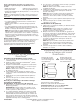
Largo del tornillo para el tipo de pared
Largo del
tornillo*
Pared de
albañilería
Vástagos
de madera
sin
cubrimiento
Placa de yeso sobre
vástagos de madera
1
⁄
2
"
(1,27 cm)
5
⁄
8
"
(1,59 cm)
3
⁄
4
"
(1,91 cm)
N.° 8 x 1
1
⁄
4
" (3,18 cm)
(no se incluye
el tornillo)
✓
N.° 8 x 2" (5,08 cm)
✓ ✓ ✓
3
⁄
16
" x 1
3
⁄
4
" (4,45 cm)
(no se incluye
el tornillo)
✓
Prepare the GearTrack®Channels
IMPORTANT:Use correct screw length for your wall type. See chart
below.
*For bare wood studs and covered walls, use an all-weather flat-head type deck screw.
For concrete block and poured masonry, use a flat-head type masonry screw.
For drywall of a thickness not listed in the chart above, see graphic below.
A
B
C
D
E
A. Drywall
B. Wooden stud
C. Flat-head screw in
every slot at every stud
D. 1" (2.54 cm) min. to 1
1
⁄
4
" (3.18 cm)
max. if near wiring
E.
1
⁄
4
"
(0.635 cm)
Tools and Parts
Gather the required tools and parts before starting installation.
Read and follow the instructions provided with any tools listed here.
Tools and Parts Needed:
• Level
• Tape measure
• Drill
• Saw
• Screws (galvanized or all-weather)
Additional Tools and Parts Needed for
Masonry Block/Poured Concrete Wall Installation:
• Hammer drill
• Caulk gun
•
3
⁄ 16" x 1
3
⁄ 4" (4.45 cm) Flat-head masonry screws (6 screws per channel)
NOTE:GearTrack® Channels can be cut and drilled with ordinary
woodworking equipment. Additional tools may be needed.
Use Requirements
• Maximum coverage per wall is 33% of the wall surface area.
• Maximum weight limit is 75 lbs (34 kg) per linear ft (30.48 cm).
• GearTrack®Channels can be mounted directly to masonry wall, ov
er
drywall to wooden studs, or to bare wooden studs.
• Intended for use in a garage or basement.
NOTE:Before installing GearTrack® Channels to masonry walls, you
must waterproof the wall to avoid mildew or foundation damage.
Walls that appear dry may actually become damp when enclosed b
y
paneling. Install the channel in accordance with all local codes and
ordinances.
Channel Spacing
If channels are to be used to support accessory hooks and/or small
item bins, they may be spaced in any way desired. If channels are to
be
used to support Gladiator® Wall GearBoxes, they must be installed 18"
(46 cm) apart.
NOTE:Wall GearBox model (GAWGB000LG0) requires the channels to
be spaced 21" (53.34 cm) apart.
• Stud nder
• AC nder
• Square
• Pencil
• Construction adhesive
•
5
⁄ 32" Masonry drill bit
18" (46 cm)
W10343308B
Screw Length for Wall Type
Screw
Length*
Masonry
Wall
Bare Wood
Studs
Drywall over Wood Studs
1
⁄2"
(1.27 cm)
5
⁄8"
(1.59 cm)
3
⁄4"
(1.91 cm)
#8 X 1
1
⁄4" (3.18 cm)
#8 X 2" (5.08 cm)
3
⁄16" X 1
3
⁄4" (4.45 cm)
(Screw Not Included)
32" (81.3 CM) AND 48" (121.9 CM)
AND 53.15" (135 CM)
GEARTRACK®CHANNEL
AND END CAP
INSTALLATION INSTRUCTIONS
(for use with Gladiator®GarageWorks products only)
(Screw Not Included)
SEGURIDAD
Si no sigue las instrucciones de inmediato, usted puede
morir o sufrir una lesión grave.
Si no sigue las instrucciones, usted puede morir o sufrir
una lesión grave.
Todos los mensajes de seguridad le dirán el peligro potencial, le dirán cómo reducir las posibilidades de sufrir una lesión y lo que
puede suceder si no se siguen las instrucciones.
Su seguridad y la seguridad de los demás es muy importante.
Hemos incluido muchos mensajes importantes de seguridad en este manual y en su electrodoméstico. Lea y obedezca siempre
todos los mensajes de seguridad.
ADVERTENCIA
PELIGRO
Este es el símbolo de alerta de seguridad.
Este símbolo le llama la atención sobre peligros potenciales que pueden ocasionar la muerte o una lesión a
usted y a los demás.
Todos los mensajes de seguridad irán a continuación del símbolo de advertencia de seguridad y de la palabra
“PELIGRO” o “ADVERTENCIA”. Estas palabras significan: