
User Manual
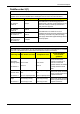
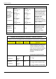
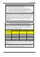
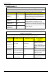
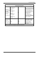
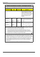
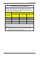

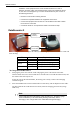
Table Of Contents
- Book 1: Setup & Maintenance
- Table of Contents
- Chapter 1
- Introduction
- Chapter 2
- Setting Up the System
- Setup Requirements
- Given Workstation
- DataRecorder and Cradle
- Storage Space for the PillCam Capsule Box
- Main Platform Components
- Connecting the Components
- Connecting the Given Workstation
- 1. Connect the Mouse cable to the Mouse connector.
- 2. Connect the Keyboard cable to the Keyboard connector.
- 3. Connect the monitor to the Workstation.
- 4. Connect the printer to the LPT connector or to the USB connector, depending on the printer’s connection cable.
- 5. If the Workstation’s voltage setting is manual, verify that the Workstation’s voltage matches the local voltage. If it does not, call Given Customer Support.
- 6. After voltage verification, connect the power cable of the Given Workstation to the electric outlet.
- 7. Connect the power cable of the monitor to the wall electric outlet.
- Connecting the DataRecorder Cradle
- Chapter 3
- Software Installation
- Chapter 4
- Multi-User Setup
- Chapter 5
- Technical Description
- System Labeling
- Essential Performance
- Warnings
- Cautions
- System Specifications
- PillCam SB Capsule
- PillCam SB 2 Capsule
- PillCam ESO 2 Capsule
- PillCam ESO 3 Capsule
- PillCam COLON 2 Capsule
- SensorArray DataRecorder 2
- SensorArray DataRecorder 3
- SB SensorBelt for DataRecorder 2 and DataRecorder 3
- DataRecorder 2 /2C
- Cradle DataRecorder 2
- DataRecorder 3
- Cradle DataRecorder 3
- DC Power Supply
- DataRecorder 3 Memory Card
- RAPID Software
- Guidance and Manufacturer's Declarations
- Chapter 6
- Maintenance
- Chapter 7
- Troubleshooting

PillCam Platform
64 Chapter 6
installation. If this equipment does cause harmful interference to radio or
television reception, which can be determined by turning the equipment off and
on, the user is encouraged to try to correct the interference by one or more of
the following measures:
• Reorient or relocate the receiving antenna.
• Increase the separation between the equipment and receiver.
• Connect the equipment into an outlet on a circuit different from that to which
the receiver is connected.
• Consult the dealer or an experienced radio/TV technician for help.
DataRecorder 2
The following table lists and explains the LEDs (from left to right) of the DataRecorder 2 Cradle and
their meaning:
To Charge the DataRecorder 2
1. First plug the power cable into the cradle and plug the power cable into the wall outlet.
All three LEDs turn on for a self-test that takes 5 seconds. After 5 seconds all LEDs turn off, and
the cradle is idle and ready for use.
If after the self-test the red LED blinks, the battery pack is faulty. Contact Given Imaging
Customer Support.
2. Insert the DataRecorder 2 or the DataRecorder 2 Li-Ion battery with its adaptor into the cradle.
All three LEDS of the cradle blink for 4 seconds, before the charging process starts (orange
LED is on).
Note
If the Cradle detects that the battery needs refreshing (i.e., the battery gauge
needs recalibration), it will automatically discharge the battery before
recharging it. The orange LED on the cradle blinks during discharging.
LED Status Explanation
Green On Battery Pack is ready for use
Orange
On Battery Pack is charging
Blinking Battery Pack is discharging
Red On Battery Pack is faulty
DataRecorder 2
with Battery
or Adaptor
Green, Orange
and Red LEDs