
User Manual
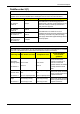
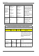
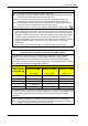
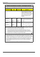
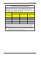

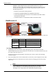
Table Of Contents
- Book 1: Setup & Maintenance
- Table of Contents
- Chapter 1
- Introduction
- Chapter 2
- Setting Up the System
- Setup Requirements
- Given Workstation
- DataRecorder and Cradle
- Storage Space for the PillCam Capsule Box
- Main Platform Components
- Connecting the Components
- Connecting the Given Workstation
- 1. Connect the Mouse cable to the Mouse connector.
- 2. Connect the Keyboard cable to the Keyboard connector.
- 3. Connect the monitor to the Workstation.
- 4. Connect the printer to the LPT connector or to the USB connector, depending on the printer’s connection cable.
- 5. If the Workstation’s voltage setting is manual, verify that the Workstation’s voltage matches the local voltage. If it does not, call Given Customer Support.
- 6. After voltage verification, connect the power cable of the Given Workstation to the electric outlet.
- 7. Connect the power cable of the monitor to the wall electric outlet.
- Connecting the DataRecorder Cradle
- Chapter 3
- Software Installation
- Chapter 4
- Multi-User Setup
- Chapter 5
- Technical Description
- System Labeling
- Essential Performance
- Warnings
- Cautions
- System Specifications
- PillCam SB Capsule
- PillCam SB 2 Capsule
- PillCam ESO 2 Capsule
- PillCam ESO 3 Capsule
- PillCam COLON 2 Capsule
- SensorArray DataRecorder 2
- SensorArray DataRecorder 3
- SB SensorBelt for DataRecorder 2 and DataRecorder 3
- DataRecorder 2 /2C
- Cradle DataRecorder 2
- DataRecorder 3
- Cradle DataRecorder 3
- DC Power Supply
- DataRecorder 3 Memory Card
- RAPID Software
- Guidance and Manufacturer's Declarations
- Chapter 6
- Maintenance
- Chapter 7
- Troubleshooting

Technical Description
Chapter 5 57
NOTE 1: At 80 MHz and 800 MHz, the higher frequency range applies.
NOTE 2: These guidelines may not apply in all situations. Electromagnetic propagation is affected by
absorption and reflection from structures, objects and people.
NOTE 3: P is the maximum output power rating of the transmitter in watts (W) according to the
transmitter manufacturer and d is the recommended separation distance in meters (m).
NOTE 4: Field strengths from fixed RF transmitters, as determined by an electromagnetic site survey
a
,
should be less than the compliance level in each frequency range
b
.
NOTE 5: Interference may occur in the vicinity of equipment marked with the following symbol:
a Field strengths from fixed transmitters, such as base stations for radio (cellular/cordless) telephones
and land mobile radios, amateur radio, AM and FM radio broadcast and TV broadcast cannot be
predicted theoretically with accuracy. To assess the electromagnetic environment due to fixed RF
transmitters, an electromagnetic site survey should be considered. If the measured field strength in
the location in which the DataRecorder 2 is used exceeds the applicable RF compliance level
above, the DataRecorder 2 should be observed to verify normal operation. If abnormal performance
is observed, additional measures may be necessary, such as re-orienting or relocating the
DataRecorder 2.
b Over the frequency range 150 kHz to 80 MHz, field strengths should be less than 3 V/m.
Recommended separation distances between portable and mobile RF
communications equipment and the PillCam ESO capsule
The DataRecorder 2 is intended for use in an electromagnetic environment in which radiated RF
disturbances are controlled. The customer or the user of the DataRecorder 2 can help prevent
electromagnetic interference by maintaining a minimum distance between portable and mobile RF
communications equipment (transmitters) and the DataRecorder 2 as recommended below, according to
the maximum output power of the communications equipment.
Rated maximum
output power of
transmitter [W]
Separation distance according to frequency of transmitter [m]
150 kHz to 80 MHz
d = 1.2 P
80 MHz to 800 MHz
d = 1.2 P
800 MHz to 2,5 GHz
d = 2.3 P
0.01 Not applicable 0.12 0.23
0.1 Not applicable 0.38 0.73
1 Not applicable 1.2 2.3
10 Not applicable 3.8 7.3
100 Not applicable 12 23
For transmitters rated at a maximum output power not listed above, the recommended separation distance
d in meters (m) can be determined using the equation applicable to the frequency of the transmitter, where
P is the maximum output power rating of the transmitter in watts (W) according to the transmitter
manufacturer.
NOTE 1: At 80 MHz and 800 MHz, the separation distance for the higher frequency range applies.
NOTE 2: These guidelines may not apply in all situations. Electromagnetic propagation is affected by
absorption and reflection from structures, objects and people.
Guidance and manufacturer’s declaration - electronic emissions