
User Manual
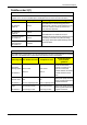
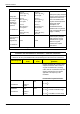
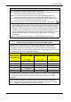
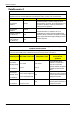
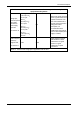
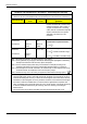
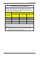

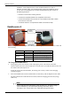
Table Of Contents
- Book 1: Setup & Maintenance
- Table of Contents
- Chapter 1
- Introduction
- Chapter 2
- Setting Up the System
- Setup Requirements
- Given Workstation
- DataRecorder and Cradle
- Storage Space for the PillCam Capsule Box
- Main Platform Components
- Connecting the Components
- Connecting the Given Workstation
- 1. Connect the Mouse cable to the Mouse connector.
- 2. Connect the Keyboard cable to the Keyboard connector.
- 3. Connect the monitor to the Workstation.
- 4. Connect the printer to the LPT connector or to the USB connector, depending on the printer’s connection cable.
- 5. If the Workstation’s voltage setting is manual, verify that the Workstation’s voltage matches the local voltage. If it does not, call Given Customer Support.
- 6. After voltage verification, connect the power cable of the Given Workstation to the electric outlet.
- 7. Connect the power cable of the monitor to the wall electric outlet.
- Connecting the DataRecorder Cradle
- Chapter 3
- Software Installation
- Chapter 4
- Multi-User Setup
- Chapter 5
- Technical Description
- System Labeling
- Essential Performance
- Warnings
- Cautions
- System Specifications
- PillCam SB Capsule
- PillCam SB 2 Capsule
- PillCam ESO 2 Capsule
- PillCam ESO 3 Capsule
- PillCam COLON 2 Capsule
- SensorArray DataRecorder 2
- SensorArray DataRecorder 3
- SB SensorBelt for DataRecorder 2 and DataRecorder 3
- DataRecorder 2 /2C
- Cradle DataRecorder 2
- DataRecorder 3
- Cradle DataRecorder 3
- DC Power Supply
- DataRecorder 3 Memory Card
- RAPID Software
- Guidance and Manufacturer's Declarations
- Chapter 6
- Maintenance
- Chapter 7
- Troubleshooting

PillCam Platform
56 Chapter 5
Voltage dips,
short interruptions
and voltage
variations on
power supply
input lines
IEC 61000-4-11
<5 % U
T
(>95 % dip in U
T
)
for 0.5 cycle
40 % U
T
(60 % dip in U
T
)
for 5 cycles
70 % U
T
(30 % dip in U
T
)
for 25 cycles
<5 % U
T
(>95 % dip in U
T
)
for 5 sec
<5 % U
T
(>95 % dip in U
T
)
for 0.5 cycle
40 % U
T
(60 % dip in U
T
)
for 5 cycles
70 % U
T
(30 % dip in U
T
)
for 25 cycles
<5 % U
T
(>95 % dip in U
T
)
for 5 sec
Mains power quality should be
that of a typical commercial or
hospital environment. If the
user of the DataRecorder 2
requires continued operation
during power mains
interruptions, it is
recommended that the
DataRecorder 2 be powered
from an uninterruptible power
supply or a battery.
Power frequency
(50/60 Hz)
magnetic field,
IEC 61000-4-8
3 A/m 3 A/m
Power frequency magnetic
fields should be at levels
characteristic of a typical
location in a typical
commercial or hospital
environment.
NOTE: U
T
is the AC mains voltage prior to application of the test level.
Guidance and manufacturer’s declaration - electronic emissions
The DataRecorder 2 is intended for use in the electromagnetic environment specified below. The
customer or the user of the DataRecorder 2 should assure that it is used in such an environment.
Immunity test
IEC 60601 test
level
Compliance
level
Electromagnetic environment -
guidance
Portable and mobile RF communications
equipment should be used no closer to
any part of DataRecorder 2, including
cables, than the recommended separation
distance calculated from the equation
applicable to the frequency of the
transmitter.
Recommended separation distance
Conducted RF
IEC 61000-4-6
3 VRMS
150 kHz to
80 MHz
3V
ms
d = 1.2 P
Radiated RF
IEC 61000-4-3
3 V/m
80 MHz to
2.5 GHz
3 V/m
d = 1.2 P 80 MHz to 800 MHz range
d = 2.3 P 800 MHz to 2.5 GHz range
Guidance and manufacturer’s declaration - electronic emissions