
User Manual
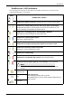
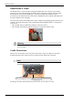
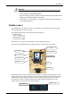
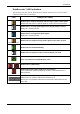
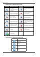
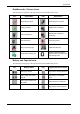
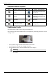
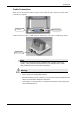
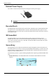
Table Of Contents
- Book 1: Setup & Maintenance
- Table of Contents
- Chapter 1
- Introduction
- Chapter 2
- Setting Up the System
- Setup Requirements
- Given Workstation
- DataRecorder and Cradle
- Storage Space for the PillCam Capsule Box
- Main Platform Components
- Connecting the Components
- Connecting the Given Workstation
- 1. Connect the Mouse cable to the Mouse connector.
- 2. Connect the Keyboard cable to the Keyboard connector.
- 3. Connect the monitor to the Workstation.
- 4. Connect the printer to the LPT connector or to the USB connector, depending on the printer’s connection cable.
- 5. If the Workstation’s voltage setting is manual, verify that the Workstation’s voltage matches the local voltage. If it does not, call Given Customer Support.
- 6. After voltage verification, connect the power cable of the Given Workstation to the electric outlet.
- 7. Connect the power cable of the monitor to the wall electric outlet.
- Connecting the DataRecorder Cradle
- Chapter 3
- Software Installation
- Chapter 4
- Multi-User Setup
- Chapter 5
- Technical Description
- System Labeling
- Essential Performance
- Warnings
- Cautions
- System Specifications
- PillCam SB Capsule
- PillCam SB 2 Capsule
- PillCam ESO 2 Capsule
- PillCam ESO 3 Capsule
- PillCam COLON 2 Capsule
- SensorArray DataRecorder 2
- SensorArray DataRecorder 3
- SB SensorBelt for DataRecorder 2 and DataRecorder 3
- DataRecorder 2 /2C
- Cradle DataRecorder 2
- DataRecorder 3
- Cradle DataRecorder 3
- DC Power Supply
- DataRecorder 3 Memory Card
- RAPID Software
- Guidance and Manufacturer's Declarations
- Chapter 6
- Maintenance
- Chapter 7
- Troubleshooting

PillCam Platform
6 Chapter 1
DataRecorder 2 Cradle
The DataRecorder 2 Cradle is used to charge the DataRecorder 2 or to charge a spare battery
externally. It is also used to discharge the battery before starting the recharge, when the Cradle
detects that the battery needs refreshing (i.e., the battery gauge needs calibration). Thus
occasionally, when inserted into the cradle, before charging starts, the Cradle may discharge first
the battery and then start recharging.
The cradle also connects the DataRecorder 2 to the computer for performing patient check-in and
creating a video.The green LED on the cradle indicates that the DataRecorder 2 is charged and
ready for use.
• The red LED, when lit continuously, indicates a defective battery.
• The red LED, when blinking, indicates that there is a problem with the cradle.
Warning
Never connect the DataRecorder 2 to the SensorArray while the DataRecorder
2 is in its cradle.
Cradle Connections
There are four connections on the back panel of the cradle. Only two of them are used with
standard operation of the cradle: the power connector and the USB cable connection.
Note
When connecting more than one DataRecorder 2 to the computer, it is
recommended to use a USB-powered hub.
The D-type connector and Auxiliary mains socket-outlet are for service use only.
Auxiliary mains socketD-type connector
USB cable
Power connector