
User's Manual


4.4 Mini-PCIe 1 Module Installation
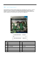
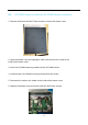
1. Remove the bottom four M2.5*5mm screws to remove the bottom cover.
2. Open the bottom cover and unplug the cable connected to the board on the
inside of the bottom cover.
38
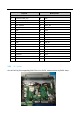
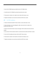
3. Remove the two M2.5*6mm screws securing the DIO module and remove the DIO
module.
4. Remove the M2.5*8mm screw to securing the IOM-2RG module and remove the
IOM-2RG module.
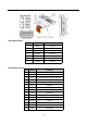
5. Remove the Plastic Pillars.
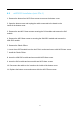
6. Insert the mini-PCIe card module into the mini-PCIe1 socket and secure with M2.5*6mm
screw.
7. Install the Plastic Pillars.
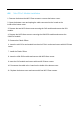
8. Insert the IOM-2RG module and secure with M2.5*8mm screw.
9. Insert the DIO module and secure with two M2.5*6mm screws.
10. Reconnect the cable to the board on the inside of the bottom cover.
11. Replace the bottom cover and secure with four M2.5*5mm screws.