
User's Manual

3.3.3 UART Ports
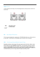
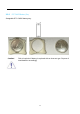
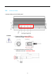
Two RS-232/422/485 ports and two RS-232 ports on the rear panel for communicating with
external devices. COM1~COM4 are located on the rear panel via 9-pin D-Sub male
connectors. COM 1/2 can be configured for full RS-232, RS-422 or RS-485 with auto flow
control communication. Mode selection is by BIOS, the default definition is RS-232.
Each of the serial ports individually contains a programmable baud rate generator which is
capable of dividing the input clock by a number ranging from 1 to 65535. The data rate of
each serial port can be programmed from 115.2K baud (COM1 baud rate up to 912.6Kbit/s)
and down to 50 baud. The character options are programmable for 1 start bit; 1, 1.5 or 2
stop bits; even, odd, stick or no parity; and privileged interrupts. Each port supports 128
bytes RX FIFO depths and 16 bytes TX FIFO depths.
All transmitter outputs and receiver inputs feature robust electrostatic discharge (ESD)
protection to ±15kV Human Body Model (HBM) and ±8kV IEC- 61000-4-2 Contact. Each
receiver output has full fail-safe protection to avoid system lockup, oscillation, or
indeterminate states by defaulting to logic-high output level when the inputs are open,
shorted, or terminated but undriven.
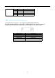
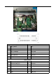
The following table describes the pin definition of UART ports.
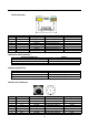
COM1, COM2:
22
UART mode RS-232
RS-422
(5-wire)
RS-422
(9-wire)
RS-485
(3-wire)
D-Sub 9 Male
COM1,COM2
Pin 1 DCD# TxD- TxD- Data-
Pin 2 RxD TxD+ TxD+ Data+
Pin 3 TxD RxD+ RxD+ -
Pin 4 DTR# RxD- RxD- -
Pin 5 GND GND GND GND
Pin 6 DSR - RTS- -
Pin 7 RTS# - RTS+ -
Pin 8 CTS# - CTS+ -
Pin 9 RI# - CTS- -
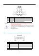
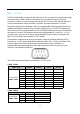
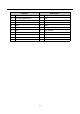
COM3, COM4:
UART mode RS-232 Description
D-Sub 9 Male
COM3,COM4
Pin 1 DCD# Data Carrier Detect
Pin 2 RxD Receive Data
Pin 3 TxD Transmit Data
Pin 4 DTR# Data Terminal Ready