
User's Manual
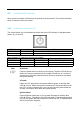
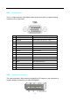
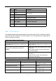

Pin
Name
Description
1
VBus
+5V
Power
2
USB
D-
USB 2.0 data
3
USB D+
4
GND
Ground for power return
5
StdA_SSRX
- SuperSpeed receiver
6
StdA_SSRX+
SuperSpeed receiver
7
GND_DRAIN
Ground for signal return
8
StdA_SSTX
- SuperSpeed transmitter
9
StdA_SSTX+
SuperSpeed transmitter
17
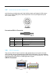
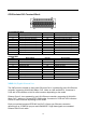
3.2.9 GPIO/Isolated DIO
16-bit digital programmable general-purpose input and output (GPIO) is standard. Isolated
8-bit DI & 8-bit DO is optional. The GPIO support 3.3V or 5V signal and are configurable by
BIOS or Application Program.
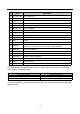
DI/DO Safety-Related Certifications:
DI
DO
2500
-V PART NUMBER PACKAGE BODY
SIZE
(NOM) RMS Isolation for 1 minute per UL
1577
2500
-V PART NUMBER PACKAGE BODY
SIZE
(NOM) RMS Isolation for 1 minute per UL
1577
Approved
by VDE, DIN EN60747-5-2(_) (as an
option),
file No. 40009162 (as model No.
PC3H4
)
4242
-V ISO7131CC PK Isolation per DIN V
VDE
V
0884-10
(VDE
V 0884-10):2006-12, 566 V ISO7140CC
PK Working
Voltage
UL flammability
grade (94V-0)
CSA
Component Acceptance Notice 5A, IEC
ISO7141CC
60950
-1 and IEC 61010-1 End Equipment
ISO7141FCC
Standards
CQC Certification per GB
4943.1-2011
DI/DO Operation Characteristics:
Parameter
DI
DO
Operation Voltage
5 ~ 48V
DC
Source
Mode:5 ~ 48V DC
Sink Mode:
5~40V DC
Input/Output Current Limit
25
uS
100mA
Turn On
Delay Time (Max.)
25
uS
Source
Mode: 15 uS
Sink Mode:
60uS
Turn
Off Delay Time (Max.)
25
uS
Source
Mode: 15 uS
Sink Mode:
60uS