
User's Manual
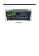
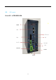

3.2 Front Panel I/O Functions
Most common computer I/O functions are placed on the front panel. This section describes
each I/O function on the front panel.
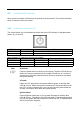
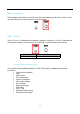
3.2.1 Power Button with Power LED
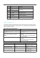
The Power Button is a non-latched switch with dual color LED indicator. It indicates power
status: S0, S3 and S5.
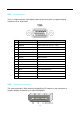
LED Color Power Status System Status
Solid Blue S0 System working
Solid Orange S3, S5 Suspend to RAM, System off with standby power
12
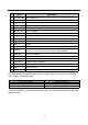
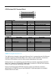
More detailed LED indications are listed as follows:
Power Mode Power On Power Off Suspend to RAM, Hibernate
ATX Mode Solid Blue Solid Orange Solid Orange
AT Mode Solid Blue - -
Ignition Mode Solid Blue - -
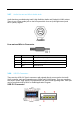
ATX Mode:
Press the power button to power on the system. The blue LED will turnon.
When the system is powered off, the orange LED will turn on. In case of
system error, press the power button for at least 4 seconds to shut down
the system directly.
AT Mode:
Plug in the DC input power, the system will auto power on and the blue
LED will turn on. When the system is powered off, the system will turn-off
the LED. In case of system error, you can just press the power button for
at least 4 seconds to shut down the system directly
Ignition Mode:
External ignition switch turn-on, the system will power on and the blue
LED will turn on. Then plug in the DC input power. External ignition switch
turn-off, the system will turn off and the LED will turn off. The powerbutton
will be not function at ignition.
Note
☞