IoTEDGE3100M Fanless Embedded System Hardware User’s Manual Revision 1.
Contents …………………………………………………………………………………………ii Contents ………………………………………………………………………………………...vi Preface Chapter 1 General Introduction .................................................................................... 1 Chapter 2 Mechanical Dimensions................................................................................ 7 Chapter 3 Hardware Function Description .................................................................. 10 Chapter 4 Hardware Installation ..................................
Chapter 1 General Introduction 1 This chapter includes: Overview System Features System Specification Power Specification Supported CPU List Packing List Ordering Information
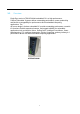
1.1 Overview Eagle Eyes series IoTEDGE3100M embedded PC is a high-performance. Fanless Embedded Systems deliver outstanding performance, power productivity and flexible manageability for performance-driven embedded computing applications.
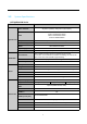
1.2 System Specifications IoTEDGE3100M Series Specifications Model Name Intel® Platform IoTEDGE3100M Skylake U (default) / Kaby lake U (by request) Core™ i7-6600U/ i7-7600U Core™ i5-6300U/ i5-7300U Core™ i3-6100U/ i3-7100U Celeron® 3955U/ 3965U CPU System Core Graphics Intel® HD Graphics 510/520; Intel® HD Graphics 610/620 Max. Memory 32GB BIOS AMI 128Mbit SPI BIOS Operating System TPM Windows / Linux SLB9665 (TPM 2.0) / SLB9635 (TPM 1.
Model Name IoTEDGE3100M Internal 2.5” Drive Bay 1x mSATA 1x (mixed with Mini-PCIe) M.2 (SATA) Storage Expansion Mechanical 1x (M Key 2242) Removable Drive Bay NA RAID Mode NA Mini-PCIe 2x PCI Express NA PCI NA IOM NA Internal USB 2.0 Dongle 1x Antenna Opening 4x 72(W) x 150(D) x 192(H) mm (2.83" x 5.91" x 7.
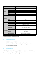
Intel® 6th Sky Lake U: Core™ i7-6600U Processor (2 cores/4 threads, 2.6 GHz/3.4 GHz, 4MB cache, 15W TDP) Core™ i5-6300U Processor (2 cores/4 threads, 2.4 GHz/3.0 GHz, 3MB cache, 15W TDP) Core™ i3-6100U Processor (2 cores/4 threads, 2.3 GHz, 3MB cache, 15W TDP) Celeron® G3955U Processor (2 cores/2 threads, 2.0 GHz, 2MB cache, 15W TDP) Intel® 7th Kaby Lake U: Core™ i7-7600U Processor (2 cores/4 threads, 2.8GHz/3.9 GHz, 4MB cache, 15W TDP) Core™ i5-7300U Processor (2 cores/4 threads, 2.6 GHz/3.
Storage Model Name Description M2-2242-SATA-32G M.2 M-key 2242 32GB SATA disk M2-2242-SATA-64G M.2 M-key 2242 64GB SATA disk M2-2242-SATA-128G M.2 M-key 2242 128GB SATA disk M2-2242-SATA-256G M.2 M-key 2242 256GB SATA disk M2-2242-SATA-32G-i M.2 M-key 2242 32GB SATA disk (Wide Temp.) M2-2242-SATA-64G-i M.2 M-key 2242 64GB SATA disk (Wide Temp.) M2-2242-SATA-128G-i M.2 M-key 2242 128GB SATA disk (Wide Temp.) M2-2242-SATA-256G-i M.2 M-key 2242 256GB SATA disk (Wide Temp.
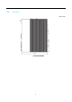
Chapter 2 Mechanical Dimensions 7 This chapter views of the dimensions, including: Top View Front View Rear View Left-Side View Right-Side View Bottom View
2.
2.
Chapter 3 Hardware Function Description 10 This chapter includes: I/O Layout Front Panel I/O Functions Rear Panel I/O Functions Right-Side Panel I/O Functions Internal I/O Functions
3.1 I/O Layout Front I/O – IoTEDGE3100M ② DDM GbE USB 3.
3.2 Front Panel I/O Functions Most common computer I/O functions are placed on the front panel. This section describes each I/O function on the front panel. 3.2.1 Power Button with Power LED The Power Button is a non-latched switch with dual color LED indicator. It indicates power status: S0, S3 and S5.
3.2.2 Reset Button The hardware Reset Button is used to reset the system without power off the system. Press the Reset Button for a few seconds to reset the system. 3.2.3 HDD LED If the LED is on, it indicates that the system’s storage is functional. If it is off, it indicates that the system’s storage is not functional. If it is flashing, it indicates data access activity. HDD LED Storage Active 4. LED Status Flash Green Dynamic Display Module (DDM) The Dynamic Display Module (DDM) is a 0.
3.2.5 VGA Connector There is a high-resolution VGA display output on the front panel. It supports display resolutions up to 1920x1080. Pin 3.2.6 Name Description 1 RED Red Video (75-ohm, 0.7 V p-p) 2 GREEN Green Video (75-ohm, 0.7 V p-p) 3 BLUE Blue Video (75-ohm, 0.
Pin Name Description 1 ML_Lane 0 (p) Lane 0 (positive) 2 GND 3 ML_Lane 0 (n) Lane 0 (negative) 4 ML_Lane 1 (p) Lane 1 (positive) 5 GND 6 ML_Lane 1 (n) Lane 1 (negative) 7 ML_Lane 2 (p) Lane 2 (positive) 8 GND 9 ML_Lane 2 (n) Lane 2 (negative) Ground Ground Ground 10 ML_Lane 3 (p) Lane 3 (positive) 11 GND Ground 12 ML_Lane 3 (n) Lane 3 (negative) 13 CONFIG1 Connected to Ground.
3.2.7 Audio Line-out and Mic-in Audio Jacks Audio functions provided using Intel® High Definition Audio and Realtek ALC892 codecs. There is one 3.5mm audio jack on the front panel with Line-out (Left/Right stereo) and Mic-in (Mono) signals. Line-out and Mic-in Connector 3.2.8 Pin Name Description 1 Mic-In Microphone input signal 2 Audio_R Right Audio out signal 3 Audio_L Left Audio out signal 4 GND Audio Ground USB 3.0 Connectors There are four USB 3.
3.2.9 Pin Name Description 1 VBus +5V Power 2 USB D- 3 USB D+ 4 GND Ground for power return 5 StdA_SSRX- SuperSpeed receiver 6 StdA_SSRX+ SuperSpeed receiver 7 GND_DRAIN Ground for signal return 8 StdA_SSTX- SuperSpeed transmitter 9 StdA_SSTX+ SuperSpeed transmitter USB 2.0 data GPIO/Isolated DIO 16-bit digital programmable general-purpose input and output (GPIO) is standard. Isolated 8-bit DI & 8-bit DO is optional. The GPIO support 3.
GPIO/Isolated DIO Terminal Block Programmable DIO Pin 1 2 3 4 5 6 7 8 9 10 Description GPIO10 (Default GPI bit0) GPIO11 (Default GPI bit1) GPIO12 (Default GPI bit2) GPIO13 (Default GPI bit3) GPIO14 (Default GPI bit4) GPIO15 (Default GPI bit5) GPIO16 (Default GPI bit6) GPIO17 (Default GPI bit7) Digital Input COM GND Pin No.
RJ45 Connector Pin No 1 2 3 4 5 6 7 8 10 / 100 Mbps TX+ TXRX+ RX- 1000 Mbps BI_DA+ BI_DABI_DB+ BI_DC+ BI_DCBI_DBBI_DD+ BI_DD- Description Bi-directional pair A + Bi-directional pair A Bi-directional pair B + Bi-directional pair C + Bi-directional pair C Bi-directional pair B Bi-directional pair D + Bi-directional pair D - PoE (optional) PoE+ PoE+ PoEPoE- Ethernet Active/Link LEDs Active/Link LED (left) Off Solid Yellow Flashing Yellow Status Disconnected Connected, no data transmission Connected, dat
3.2.11 PoE LEDs 4 LEDs indicate the PoE status. The LED will light when the PoE port links to PoE PD of each device. Note ☞ 3.3 The photo is only IoTEDGE3100M. Rear Panel I/O Functions To fit more general application requirements, IoTEDGE3100M offers more I/O functions on its rear panel. In this section, we’ll illustrate each I/O function on the rear panel. 3.3.1 3-Pin Euro type Terminal Block for System DC Input Eagle Eyes AI allows a wide range of DC power input from 9V to 36Vdc.
Pin Name 1 DC V+ DC INPUT + 2 DC V- DC INPUT - 3 Ground Caution! 3.3.2 Description Earth Ground or Chassis Ground 1. Make sure the polarity of the power plug is correct before plugging it into the system. 2. Please make sure the voltage of DC power supply is correct before you connect it to the IoTEDGE3100M system. Supplying a voltage over 36V will damage the system.
3.3.3 UART Ports Two RS-232/422/485 ports and two RS-232 ports on the rear panel for communicating with external devices. COM1~COM4 are located on the rear panel via 9-pin D-Sub male connectors. COM 1/2 can be configured for full RS-232, RS-422 or RS-485 with auto flow control communication. Mode selection is by BIOS, the default definition is RS-232.
Pin 5 Pin 6 Pin 7 Pin 8 Pin 9 3.3.4 GND DSR RTS# CTS# RI# System Ground Data Set Ready Request to Send Clear to Send Ring Indicator Wireless module LED for Mini-PCIe 2 ports Mini-PCIe sockets , it can support any WWAN/WLAN/WPAN Mini-PCIe wireless module, such as Wi-Fi . When a Mini-PCIe wireless module is installed and activited, the corresponding LED will light as described below.
3.3.5 RTC CMOS Battery Tray Swappable RTC CMOS battery tray. Caution! Risk of explosion if battery is replaced with an incorrect type. Dispose of used batteries accordingly.
3.4 Antenna Holes 4 antenna holes on its left-side panel Caution! 1. Proposed SMA connector SPEC: SMA screw length "minimum 10mm" 2.
3.5 Internal I/O Functions In addition to I/O connectors on the front/rear panel, the IoTEDGE3100M system provides other useful features via its on-board connectors, such as mSATA socket, Mini-PCIe sockets. This section describes these internal I/O functions. There are two on-board full-length Mini PCI Express slots . Many off-the-shelf MiniPCIe modules with versatile capabilities are available. By installing a Mini-PCIe module, your system can have expanded features such as Wi-Fi 3.5.
Top Side Bottom Side 1 PCIe_Wake# 2 3.3V 3 Reserved 4 GND 5 Reserved 6 1.5V 7 PCIe_CLKREQ# 8 UIM_PWR 9 GND 10 UIM_DATA 11 PCIe_REFCLK- 12 UIM_CLK 13 PCIe_REFCLK+ 14 UIM_RESET 15 GND 16 UIM_VPP Mechanical key 17 Reserved (UIM_C8) 18 GND 19 Reserved (UIM_C4) 20 Reserved 21 GND 22 PCIe_RST# 23 PCIe_PERn0/SATA-Tx+ 24 +3.3V_SB 25 PCIe_PERp0/SATA-TX- 26 GND 27 GND 28 +1.
Top Side Bottom Side 31 PCIe_PETn0/SATA-RX- 32 SMB_DATA 33 PCIe_PETp0/SATA-RX+ 34 GND 35 GND 36 USB_D- 37 GND 38 USB_D+ 39 +3.3V 40 GND 41 +3.3V 42 LED_WWAN# 43 GND 44 LED_WLAN# 45 Reserved 46 LED_WPAN# 47 Reserved 48 +1.5V 49 Reserved 50 GND 51 Reserved 52 +3.
3.5.3 Mini PCI Express Socket 2 Full-length Mini PCI Express Socket supports Full Length Mini-PCIe, USB 2.0. This slot allows your system to connect to the Internet through available telecom operator’s network. For WIF communication, the IoTEDGE3100M system provides multiple SMA antenna apertures on the left panel for multi-antenna configuration. Top Side Bottom Side 1 PCIe_Wake# 2 3.3V 3 Reserved 4 GND 5 Reserved 6 1.
Top Side Bottom Side Mechanical key 17 Reserved (UIM_C8) 18 GND 19 Reserved (UIM_C4) 20 Reserved 21 GND 22 PCIe_RST# 23 PCIe_PERn0 24 +3.3V_SB 25 PCIe_PERp0 26 GND 27 GND 28 +1.5V 29 GND 30 SMB_CLK 31 PCIe_PETn0 32 SMB_DATA 33 PCIe_PETp0 34 GND 35 GND 36 USB_D- 37 GND 38 USB_D+ 39 +3.3V 40 GND 41 +3.3V 42 LED_WWAN# 43 GND 44 LED_WLAN# 45 Reserved 46 LED_WPAN# 47 Reserved 48 +1.5V 49 Reserved 50 GND 51 Reserved 52 +3.3V 3.5.4 M.
Pin 1 3 5 7 9 11 13 15 17 19 21 23 25 27 29 31 33 35 37 39 41 43 45 47 49 51 53 55 57 67 69 71 73 3.5.5 Description Pin Description Ground 2 VCC 3.3V Ground 4 VCC 3.3V 6 8 Ground 10 LED# 12 VCC 3.3V 14 VCC 3.3V Ground 16 VCC 3.3V 18 VCC 3.
SATA Data Pinout Pin Name Function 1 GND Ground 2 A+ Transmit+ 3 A- Transmit- 4 GND Ground 5 B- Receive- 6 B+ Receive+ 7 GND Ground SATA Power Pinout Pin Name Function 1 NC N 2 NC 3.3V Power 3 NC 3.
3.5.6 Internal USB 2.0 Ports One internal USB 2.0 Type A connector. The internal USB port is designed to allow users to attach a protection dongle inside the chassis.
Chapter 4 This chapter describes how to install parts, including: Hardware Installation 34 SO-DIMM Memory Installation M.2 SSD Installation MSATA SSD Installation Mini-PCIE 1 Module Installation Mini-PCIE 2 Module Installation 2.
4.1 SO-DIMM Memory Installation SO-DIMM Memory Installation 1. Remove the bottom four M2.5*5mm screws to remove the bottom cover. 2. Open the bottom cover and unplug the cable connected to the board on the inside of the bottom cover. 3. Insert the SO-DIMM memory module into the SO-DIMM socket. 4. Confirm that the SO-DIMM is securely inserted into the socket. 5. Reconnect the cable to the board on the inside of the bottom cover. 6. Replace the bottom cover and secure with four M2.5*5mm screws.
3. Insert the SO-DIMM memory module into the SO-DIMM socket. 4. Confirm that the SO-DIMM is securely inserted into the socket. 5. Reconnect the cable to the board on the inside of the bottom cover. 6. Replace the bottom cover and secure with four M2.5*5mm screws. 4.2 M.2 SSD Installation 1. Remove the bottom four M2.5*5mm screws to remove the bottom cover. 2. Open the bottom cover and unplug the cable connected to the board on the inside of the bottom cover. 3. Remove the two M2.
4.3 mSATA SSD Installation (mini-PCIe 1) 1. Remove the bottom four M2.5*5mm screws to remove the bottom cover. 2. Open the bottom cover and unplug the cable connected to the board on the inside of the bottom cover. 3. Remove the two M2.5*6mm screws securing the DIO module and remove the DIO module. 4. Remove the M2.5*8mm screw to securing the IOM-2RG module and remove the IOM-2RG module. 5. Remove the Plastic Pillars. 6. Insert the mSATA module into the mini-PCIe1 socket and secure with M2.5*6mm screw.
4.4 Mini-PCIe 1 Module Installation 1. Remove the bottom four M2.5*5mm screws to remove the bottom cover. 2. Open the bottom cover and unplug the cable connected to the board on the inside of the bottom cover. 3. Remove the two M2.5*6mm screws securing the DIO module and remove the DIO module. 4. Remove the M2.5*8mm screw to securing the IOM-2RG module and remove the IOM-2RG module. 5. Remove the Plastic Pillars. 6. Insert the mini-PCIe card module into the mini-PCIe1 socket and secure with M2.
4.5 Mini-PCIe 2 module installation 1. Remove the bottom four M2.5*5mm screws to remove the bottom cover. 2. Open the bottom cover and unplug the cable connected to the board on the inside of the bottom cover. 3. Remove the two M2.5*6mm screws securing the DIO module and remove the DIO module. 4. Insert the Mini-PCIe module into the Mini-PCIe Socket 2 and secure with M2.5*6mm screw. 5. Insert the DIO module and secure with two M2.5*6mm screws. 6.
4.6 2.5” SATA HDD/SSD Installation 1. Remove the bottom four M2.5*5mm screws to remove the bottom cover. 2. Open the bottom cover and unplug the cable connected to the board on the inside of the bottom cover. 3. Remove the two M2.5*6mm screws securing the DIO module and remove the DIO module. 4. Remove the M2.5*8mm screw to securing the IOM-2RG module and remove the IOM-2RG module. 5. Remove the Plastic Pillars. 6. Remove the IOM-POEAT4 module. 7.
4.7 Replace CMOS RTC Battery 1. Remove the two M2.5*8mm screws securing the rear panel battery cover. 2. Open the battery cover and pull out the white battery tray holder.
3. Remove the CR2032 button battery from the white battery tray holder and replace it with a new one. + Caution! + 1. When changing the battery, make note of the polarity of the battery. 2. When the battery tray holder is inserted back into the battery slot, make sure that positive (+) is facing up. 4. Insert the battery tray holder into the battery holder and secure the rear panel battery cover with 2 M2.5 screws.
4.8 Mounting Bracket Installation 1. Secure 2 brackets to the bottom cover with 2 M2.5x5 screws.
Chapter 5 This chapter includes: Function Settings 44 Clear CMOS/ME Switch (SW1)
5.1 Clear CMOS/ME Switch (SW1) You can use Switch SW1 to clear CMOS and Intel® Management Engine settings.
Chapter 6 This chapter includes: Function Settings 46 Wifi module model
Wifi module model BCM943224HMPx P201 47
Wifi module model Quick Details Place of Origin: China Brand Name: Broadcom Model Number: BCM943224HMP Type: Wireless Interface Type: Mini Pcie Transmission Rate: 300Mbps Application: Laptop Kind: Internal Products Status: Stock Spare Part Number: 593837-001 Application: This item do not compatible with Hp and Lenovo Support OS: Mac Hackintosh and Windows xp/win7/8/8.
Wifi module model Product Description Wireless BCM943224HMP 593837-001 Dual Band 300M Mini Pcie Wifi Card Spare Part Number: 593837-001 Manufacturer: Broadcom Model: BCM943224HMP Interface: Mini pci-e Speed Up to: 300Mbps Standard: IEEE802.11 b/g/n Suppot: Mac Hackintosh and Windows xp/win7/8/8.1/vista/Linux,DO NOT compatible with Hp and Lenovo.
Appendices This section includes: 51 Appendix A: DisplayPort MultiStream Transport (MST) Capabilities Appendix B: How To Use GPIO
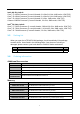
Appendix A: DisplayPort Multi-Stream Transport (MST) Capabilities The IoTEDGE3100M system DisplayPorts support Multi-Stream Transport (MST). MST 1 display 2 concurrent Note ☞ Max. Resolution Pixel Clock 3840x2160 @60Hz 4096x2304 @60Hz 2880x1800 @60Hz 533.25 605.0 337.75 One Display Total Bandwidth for Bandwidth [Gbps] all display [Gbps] 16 16 18.5 18.15 10.13 20.26 1.Multi-Stream Transport (MST) enables multiple monitors via a single DisplayPort* connector. 2.
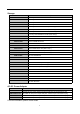
Appendix B: How to use GPIO Functional Description GPIO signals are accessed via a 2.54mm 2x10-pin terminal block, including lsolated DI 8 bit, DO 8 bit, DI Com, Power and GND. DI/DO supports NPN (Sink) and PNPO (Source) mode. DI mode is selected by external H/W connection. DO mode is selected by BIOS setting or Application Program.
Pin Define Pin 1 2 3 4 5 6 7 8 9 10 Description Isolated DI bit0 Isolated DI bit1 Isolated DI bit2 Isolated DI bit3 Isolated DI bit4 Isolated DI bit5 Isolated DI bit6 Isolated DI bit7 Digital Input COM Isolated GND Pin 11 12 13 14 15 16 17 18 19 20 Description Isolated DO bit0 Isolated DO bit1 Isolated DO bit2 Isolated DO bit3 Isolated DO bit4 Isolated DO bit5 Isolated DO bit6 Isolated DO bit7 Isolated GND Isolated VCC Isolation Digital Input Connection Method Digital Input Sink Mode Connection Method
Digital Input Source Mode Connection Method Pin 9 digital input COM pin connection to V-. Input pin (Pins 1-8) control by V+. DC 5-48V Isolation Digital Output Connection Method Digital Output Sink Mode Connection Method Digital Input Sink Mode Internal Circurt Current input to system, Control Low status Pin No. 11-18 DC 5-40V Digital Output Source Mode Connection Method Digital Input Source Mode Internal Circurt Current Ouput to device, Control High state DI VCC Pin No.
20C