
User Guide


GNU Image Manipulation Program
537 / 653
Bump Map This drop-down list allows you to select the image that will be used as a map for bumpmapping. This list contains
images that are present on your screen when you launch the filter. Images opened after starting filter are not present in this
list.
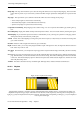
Map Type This option allows you to define the method that will be used when creating the map image:
• Linear: bump height is a direct function of luminosity.
• Sinusoidal: bump height is a sinusoidal function of luminosity.
• Spheric: bump height is a spheric function of luminosity.
Compensate for darkening Bumpmapping tends to darken image. You can compensate this darkening by checking this op-
tion.
Invert Bumpmap Bright pixels default to bumps and dark pixels to hollows. You can invert this effect by checking this option.
Tile bumpmap If you check this option, there will be no relief break if you use your image as a pattern for a web page: patterns
will be placed side by side without any visible joins.
Azimut Azimut: This is about lighting according to the points of the compass (0 - 360). East (0) is on the left. Increasing value
goes counter-clockwise.
Elevation Elevation: That’s height from horizon (0), up to zenith (90).
Depth With this slider, you can vary bump height and hollow depth. The higher the value, the higher the difference between
both. Values vary from 0 to 100.
X/Y offsets With this slider, you can adjust the map image position compared with the image, horizontally (X) and/or vertically
(Y).
Sea Level If your image has transparent areas, they will be treated like dark areas and will appear as hollows after bumpmap-
ping. With this slider, you can reduce hollows as if sea level was raising. This hollows will disappear when sea level value
reaches 255. If the Invert Bumpmap option is checked, transparent areas will be treated as bright areas, and then Sea Level
slider will plane bumps down.
Ambient This slider controls the intensity of ambient light. With high values, shadows will fade and relief lessen.
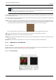
15.12.3 Displace
15.12.3.1 Overview
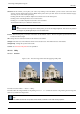
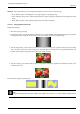
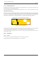
Figure 15.199: Displacement examples
X displacement coefficient is 30 (with a negative coefficient displacement would be inverse). Vacated pixels are black. The
displacement map has four grey stripes with values of 210, 160, 110, and 60, respectively. The image areas corresponding to
light gray (≥128) were displaced 19 and 8 pixels to the left. The image areas corresponding to dark gray (≤127) were displaced
4 and 15 pixels to the right.
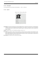
You can find this filter through Filters → Map → Displace