
User guide


are what are called ‘insulation displacement connectors’. These simply snap on to an entire
cable, automatically ‘displacing’ the wire insulation and making contact with the wires within.
This means that an entire 40 wire cable can be terminated in seconds. All connectors are po-
larized, to keep them from being plugged in backwards.
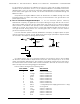
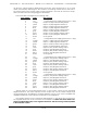
Each J6/A cable is arranged in the following order:
wire number color wire function
1 brown circuit ground
2 red + unregulated power supply (protected to 1 amp)
3 orange Output 15 (0Fh) Positive Analog Output
4 yellow Output 15 (0Fh) Negative Reference
5 green Output 14 (0Eh) Positive Analog Output
6 blue Output 14 (0Eh) Negative Reference
7 violet Output 13 (0Dh) Positive Analog Output
8 gray Output 13 (0Dh) Negative Reference
9 white Output 12 (0Ch) Positive Analog Output
10 black Output 12 (0Ch) Negative Reference
11 brown circuit ground
12 red + unregulated power supply (protected to 1 amp)
13 orange Output 11 (0Bh) Positive Analog Output
14 yellow Output 11 (0Bh) Negative Reference
15 green Output 10 (0Ah) Positive Analog Output
16 blue Output 10 (0Ah) Negative Reference
17 violet Output 9 (09h) Positive Analog Output
18 gray Output 9 (09h) Negative Reference
19 white Output 8 (08h) Positive Analog Output
20 black Output 8 (08h) Negative Reference
21 brown circuit ground
22 red + unregulated power supply (protected to 1 amp)
23 orange Output 7 (07h) Positive Analog Output
24 yellow Output 7 (07h) Negative Reference
25 green Output 6 (06h) Positive Analog Output
26 blue Output 6 (06h) Negative Reference
27 violet Output 5 (05h) Positive Analog Output
28 gray Output 5 (05h) Negative Reference
29 white Output 4 (04h) Positive Analog Output
30 black Output 4 (04h) Negative Reference
31 brown circuit ground
32 red + unregulated power supply (protected to 1 amp)
33 orange Output 3 (03h) Positive Analog Output
34 yellow Output 3 (03h) Negative Reference
35 green Output 2 (02h) Positive Analog Output
36 blue Output 2 (02h) Negative Reference
37 violet Output 1 (01h) Positive Analog Output
38 gray Output 1 (01h) Negative Reference
39 white Output 0 (00h) Positive Analog Output
40 black Output 0 (00h) Negative Reference
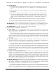
Analog loads are connected between each of the Positive outputs and its associated
Negative reference. The output capacity of each output is 20 ma. The output voltage range
can be adjusted from the FSK/RTU to anywhere between 0 and 10 volts. Current amplifiers are
available if additional current capacity is required for your application.
The negative reference is at a voltage of approximately 1.6 volts above the circuit ground.
The negative references are all connected on the FSK/RTU, but there must be no direct con-
nections made between any of the negative references and the circuit grounds anywhere
in the animation system.
GILDERFLUKE & CO. • 205 SOUTH FLOWER ST. • BURBANK, CALIF. 91502-2102 • 818/840-9484 • FAX818/840-9485
6 of 25