
Manual


the ÔPreferencesÕ pulldown). If it is defined as eight digital channels, you can just draw in the
binary data as needed.
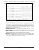
q) Moog Status on DMX: This is a Moog Mode specific command. The outgoing stream of DMX-
512 data from the BS-Serial always contains the same data as is in the Eproms or is being re-
ceived via the DMX-512 input. When a DMX-512 channel other than 255/FFh is selected using
this command, the status from the Moog Motion Base will be transmitted in the DMX-512 data
stream. This can be received by any DMX-compatible receivers for display or diagnostics.
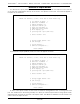
The status is sent out in 11 bytes of the DMX-512 data. The bytes are used as follows:
byte 0: Actuator A Feedback MSB
byte 1: Actuator B Feedback MSB
byte 2: Actuator C Feedback MSB
byte 3: Actuator D Feedback MSB
byte 4: Actuator E Feedback MSB
byte 5: Actuator F Feedback MSB
byte 6: Moog Status 0
Bit 7: MoogFault3
Bit 6: MoogFault2
Bit 5: MoogParking
Bit 4: MoogRun
Bit 3: MoogEngaged
Bit 2: MoogStandby
Bit 1: MoogIdle
Bit 0: MoogPowerUp
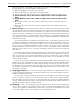
byte 7: Moog Status 1
Bit 7: MoogFault
Bit 6: MoogStandbyEngaged
Bit 5: MoogPowerupIdle
Bit 4: MoogInDOFMode
Bit 3: MoogInLengthMode
Bit 2: MoogSnubber
Bit 1: MoogInhibited
Bit 0: MoogDisabled
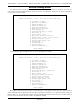
byte 8: Discrete I/O information
Bit 7: Always = 1
Bit 6: amplifier enable command
Bit 5: drive bus sense
Bit 4: limit shunt command
Bit 3: limit switch sense
Bit 2: amplifier fault sense
Bit 1: motor thermal fault sense
Bit 0: base at home
byte 9: latched fault information
Bit 7: Always = 1
Bit 6: limit fault declared
Bit 5: drive bus declared
Bit 4: amplifier fault declared
Bit 3: communications fault declared
Bit 2: homing fault declared
Bit 1: envelope fault declared
Bit 0: torque monitor fault declared
byte 10: latched fault information
Bit 7: Always = 0
Bit 6: idle rate fault declared
Bit 5: motor thermal fault declared
GILDERFLUKE & C
O
.¥ 205 S. FLOWER ST. ¥ BURBANK, CA 91502 ¥ 818/840-9484 ¥ 800/776-5972 ¥ FAX 818/840-9485
40 of 48