
Manual

BackPlane Connections:
The BackPlane connection is through a sixty position double sided edge connector (thirty connections
on each side on .1Ó centers). This normally is plugged into a card cage, but can also be used with an IDS
or other discrete edge connector.
The first ten positions are used for the Smart Brick network and RS-422 serial port used by other cards in
the system. They are normally bussed between all of the cards in the card cage (although they can be
separated by cutting the lines if desired). The BS-DMX-Tx and BS-Serial do not use these bussed serial port
lines.
The next forty positions are used to connect the BS-DMX-Tx or BS-Serial Smart Bricks to the output ca-
bling. It is on these pins that most of the I/O connections are made.
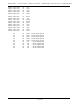
The last ten positions are used to provide power to the BS-DMX-Tx or BS-Serial Smart Bricks. These wires
are ganged to provide a higher current carrying capacity. The pinout of this connector is as follows:
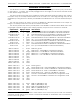
output wire # Edge pin #color wire function
Smart Brick net #2 1 black Smart Brick Network Data/ into BS-DMX-Tx or BS-Serial Smart Bricks
Smart Brick net #1 2 white Smart Brick Network Data into BS-DMX-Tx or BS-Serial Smart Bricks
Smart Brick net #3 3 red Smart Brick Network Clock into BS-DMX-Tx or BS-Serial Smart Bricks
Serial Port #3 4 red TxD + out (not used by BS-DMX-Tx or BS-Serial Smart Bricks)
Smart Brick net #4 5 green Smart Brick Network Clock/ into BS-DMX-Tx or BS-Serial Smart Bricks
Serial Port #2 6 black TxD - out (not used by BS-DMX-Tx or BS-Serial Smart Bricks)
Smart Brick net #5 7 yellow Smart Brick Network Strobe into BS-DMX-Tx or BS-Serial Smart Bricks
Serial Port #5 8 yellow Rx + in (not used by BS-DMX-Tx or BS-Serial Smart Bricks)
Smart Brick net #6 9 blue Smart Brick Network Strobe into BS-DMX-Tx or BS-Serial Smart Bricks
Serial Port #4 10 green Rx -in (not used by BS-DMX-Tx or BS-Serial Smart Bricks)
Ribbon cable #1 11 brown DMX-512 ground
Ribbon cable #2 12 red DMX-512 Rx - into BS-DMX-Tx or BS-Serial Smart Bricks
Ribbon cable #3 13 orange DMX-512 Rx + into BS-DMX-Tx or BS-Serial Smart Bricks
Ribbon cable #4 14 yellow DMX-512 Tx - out of BS-DMX-Tx or BS-Serial Smart Bricks
Ribbon cable #5 15 green DMX-512 Tx + out of BS-DMX-Tx or BS-Serial Smart Bricks
Ribbon cable #6 16 blue
Ribbon cable #7 17 violet
Ribbon cable #8 18 gray
Ribbon cable #9 19 white
Ribbon cable #10 20 black
Ribbon cable #11 21 brown RS-422 ground
Ribbon cable #12 22 red RS-422 Serial Port Rx - data into BS-DMX-Tx or BS-Serial Smart Bricks
Ribbon cable #13 23 orange RS-422 Serial Port Rx + data into BS-DMX-Tx or BS-Serial Smart Bricks
Ribbon cable #14 24 yellow RS-422 Serial Port Tx - data out of BS-DMX-Tx or BS-Serial
Ribbon cable #15 25 green RS-422 Serial Port Tx + data out of BS-DMX-Tx or BS-Serial
Ribbon cable #16 26 blue Ground to force BS-DMX-Tx or BS-Serial into configuration mode
Ribbon cable #17 27 violet Ground to force BS-DMX-Tx or BS-Serial into configuration mode
Ribbon cable #18 28 gray
Ribbon cable #19 29 white
Ribbon cable #20 30 black
Ribbon cable #21 31 brown MIDI n/c (MIDI DIN pin #3)
Ribbon cable #22 32 red MIDI Tx - (MIDI DIN pin #5)
Ribbon cable #23 33 orange MIDI ground (MIDI DIN pin #2)
Ribbon cable #24 34 yellow MIDI Tx + (MIDI DIN pin #4)
Ribbon cable #25 35 green MIDI n/c (MIDI DIN pin #1)
1
GILDERFLUKE & C
O
.¥ 205 S. FLOWER ST. ¥ BURBANK, CA 91502 ¥ 818/840-9484 ¥ 800/776-5972 ¥ FAX 818/840-9485
11 of 48
1
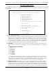
Errata: These pinouts were reversed in earlier editions of this manual. The pinout shown now has been
corrected. The Left side pin of R1 must be connected to GROUNDÊon the BS-Serial. This is the leftmost of
the two holes it can go into.