
User guide
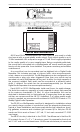
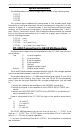

Top 1) A input negative
2) A input positive
3) B input negative
4) B input positive
5) Ground
6) Negative audio output
7) Positive audio output
8) + 5 volt supply
9) +12 to +15 volt supply
Bottom 10) -12 to -15 volt supply
CC-3251 Connections for DR-50 MiniRepeaters:
The CC-3251 card cage is the same as the CC-3250, except that the
audio outputs are through four DB-25 connectors and the trigger inputs are
through two 40 position ribbon cable connectors arranged in our standard
ÔJ6Õ. Power supply connections are identical to the CC-3250.
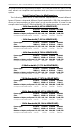
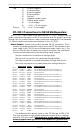
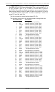
Audio Outputs: Twenty-five position female DB-25 connector. This is
used for the balanced audio outputs from the DR-50s installed in the
card cage. Each DR-50 has one balanced audio output on it. The
pinout of the the first of these connectors is as follows. The other three
connectors are identical for the remaining cardsÕ outputs.
The first connector is for cards one through eight.
The second connector is for cards nine through sixteen.
The third connector is for cards seventeen through twenty-four.
The fourth connector is for cards twenty-five through thirty-two.
SIGNAL NAME COLOR SIGNAL FUNCTION
PIN #1 Ground 1 BROWN card #1 Ground
PIN #14 + Output 1 RED card #1 Balanced Audio Line Level Positive (+)
PIN #2 - Output 1 ORANGE card #1 Balanced Audio Line Level Negative (-)
PIN #15 Ground 2 YELLOW card #2 Ground
PIN #3 + Output 2 GREEN card #2 Balanced Audio Line Level Positive (+)
PIN #16 - Output 2 BLUE card #2 Balanced Audio Line Level Negative (-)
PIN #4 Ground 3 VIOLET card #3 Ground
PIN #17 + Output 3 GRAY card #3 Balanced Audio Line Level Positive (+)
PIN #5 - Output 3 WHITE card #3 Balanced Audio Line Level Negative (-)
PIN #18 Ground 4 BLACK card #4 Ground
PIN #6 + Output 4 BROWN card #4 Balanced Audio Line Level Positive (+)
PIN #19 - Output 4 RED card #4 Balanced Audio Line Level Negative (-)
PIN #7 Ground 5 ORANGE card #5 Ground
PIN #20 + Output 5 YELLOW card #5 Balanced Audio Line Level Positive (+)
PIN #8 - Output 5 GREEN card #5 Balanced Audio Line Level Negative (-)
PIN #21 Ground 6 BLUE card #6 Ground
PIN #9 + Output 6 VIOLET card #6 Balanced Audio Line Level Positive (+)
PIN #22 - Output 6 GRAY card #6 Balanced Audio Line Level Negative (-)
PIN #10 Ground 7 WHITE card #7 Ground
PIN #23 + Output 7 BLACK card #7 Balanced Audio Line Level Positive (+)
PIN #11 - Output 7 BROWN card #7 Balanced Audio Line Level Negative (-)
PIN #24 Ground 8 RED card #8 Ground
PIN #12 + Output 8 ORANGE card #8 Balanced Audio Line Level Positive (+)
PIN #25 - Output 8 YELLOW card #8 Balanced Audio Line Level Negative (-)
PIN #13 N/C GREEN
The balanced line drivers used on the DR-50s are a SSM-2142.
This chip provides a high quality balanced output that is compen-
sated for 600 ohm lines. If
operating in single ended mode, the
unused outputs must be tied to their respective ground lines. If
you donÕt, the output will be excessively noisy.
GILDERFLUKE & CO. ¥ 205 S. FLOWER ¥ BURBANK, CA 91502-2102 ¥ 818/840-9484 ¥ 800/776-5972 ¥ FAX 818/840-9485
58 of 72