
User guide
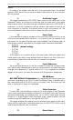
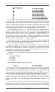

Start Inputs and Status Outputs:
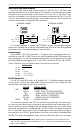
Both the 'start' inputs and 'status' output for the AB-100 or AB-Clock are
optically isolated from all other parts of the system. Connections are made
through four screw terminals on the back of the AB-100 or AB-Clock. They
can be configured to run either from the same power as the AB-100 or AB-
Clock or from external power supply. The jumper selection and connections
for these two modes of operation are as follows:
INTERNAL POWER EXTERNAL POWER
2.2KΩ
'S
TATUS'
'C
OMMON'
B I
NPUT 'RESTART'
A I
NPUT ' STA RT'
2.2KΩ
'S
TATUS'
'C
OMMON'
B I
NPUT 'RESTART'
A I
NPUT ' STA RT'
In the vast majority of cases, the ÔEXTERNALÕ power configuration is pre-
ferred, as it isolates the audio circuitry inside the AB-Clock from any possible
interference from the wires leading to your switches.
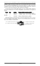
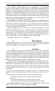
Power Supply:
Five position 180¡ DIN connector
2
. Plugging and unplugging this con-
nector from the AB-100/AB-Clock is not recommended while the power sup-
ply is plugged in. You should always unplug the power supply from the wall
before plugging/unplugging the 5 pin DIN connector at the AB-100/AB-
Clock. The pinout for the Power Supply connector is as follows:
SIGNAL NAME:
Pin #1 Ground
Pin #2 N/C
Pin #3 + 5 VDC
Pin #4 - 12 to 15 VDC
Pin #5 + 12 to 15 VDC
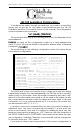
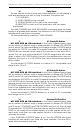
RS-422 Serial Port:
For AB-100 and AB-Clocks, a six position RJ-11 (modular telephone style
connector) is used for the serial data. Facing the end of the cable with the
release latch upwards, its pin out is as follows:
COLOR
SIGNAL NAME:
LEFT WHITE SIGNAL GROUND
BLACK - SERIAL DATA OUT FROM REPEATER
RED + SERIAL DATA OUT FROM REPEATERS
GREEN - SERIAL DATA IN TO REPEATERS
YELLOW + SERIAL DATA IN TO REPEATERS
RIGHT BLUE SIGNAL GROUND
To communicate with the AB-100 and AB-Clocks through the serial port,
you can use just about any computer or terminal that has a serial port on it.
Some newer computer designs, like the Apple Macintosh, come with serial
ports that are directly compatible with the RS-422/RS-485 signal levels the
AB-100 and AB-Clocks want to see. These signal levels are close enough to
be used with the RS-232 signal levels found on most older computers (like
all IBM PCs and compatibles). They can be attached with only a simple
GILDERFLUKE & CO. ¥ 205 S. FLOWER ¥ BURBANK, CA 91502-2102 ¥ 818/840-9484 ¥ 800/776-5972 ¥ FAX 818/840-9485
13 of 72
2 Use extreme caution when making discrete wire connections to this connection! Five
pin 180¡ DIN connectors are numbered 3, 5, 2, 4, 1 as you face the socket on the out-
side of the AudioBrick.