
Manual
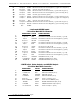

14 Analog Ref. 4 YELLOW CH. 4 (03H) Negative Reference
15 Analog Input 3 GREEN CH. 3 (02H) Positive Analog Input (19 A)
16 Analog Ref. 3 BLUE CH. 3 (02H) Negative Reference
17 Analog Input 2 VIOLET CH. 2 (01H) Positive Analog Input (20 A)
18 Analog Ref. 2 GRAY CH. 2 (01H) Negative Reference
19 Analog Input 1 WHITE CH. 1 (00H) Positive Analog Input (21 A)
20 Analog Ref. 1 BLACK CH. 1 (00H) Negative Reference
- Power Supply -
- Six Position Screw Terminal -
1 Ground (-) Sense
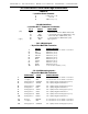
33
2 + 5 Volt Sense
34
3 -12 VDC Supply (30 A, B &C)
4 Ground
5 +12 VDC Supply (31 A, B &C)
6 + 5 VDC Supply (32 A, B &C)
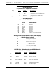
- Auxiliary Power Supply -
- Five Position 180¡ DIN Connector 35 -
1 Ground
2 Case Ground
3 + 5 VDC Supply (32 A, B &C)
4 - 12 VDC Supply (30 A, B &C)
5 + 12 VDC Supply (31 A, B &C)
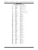
- Audio Outputs -
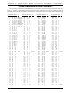
- 25 Position Female DB-25 Connector -
SIGNAL NAME COLOR SIGNAL FUNCTION
1 Ground 1 BROWN Ground (right card #0) (28 A)
14 Output 1 RED Balanced Audio Line Level Positive (+) (right card #0) (27 A)
2 Output 1 ORANGE Balanced Audio Line Level Negative (-) (right card #0) (26 A)
15 Ground 2 YELLOW Ground (left card #0) (28 C)
3 + Output 2 GREEN Balanced Audio Line Level Positive (+) (left card #0) (27 C)
16 - Output 2 BLUE Balanced Audio Line Level Negative (-) (left card #0) (26 C)
4 Ground 3 VIOLET Ground (right card #1) (28 A)
17 + Output 3 GRAY Balanced Audio Line Level Positive (+) (right card #1) (27 A)
5 - Output 3 WHITE Balanced Audio Line Level Negative (-) (right card #1) (26 A)
18 Ground 4 BLACK Ground (left card #1) (28 C)
6 + Output 4 BROWN Balanced Audio Line Level Positive (+) (left card #1) (27 C)
19 - Output 4 RED Balanced Audio Line Level Negative (-) (left card #1) (26 C)
7 Ground 5 ORANGE Ground (right card #2) (28 A)
20 + Output 5 YELLOW Balanced Audio Line Level Positive (+) (right card #2) (27 A)
GILDERFLUKE & CO. ¥ 205 SOUTH FLOWER ST. ¥ BURBANK, CALIF. 91502-2102 ¥ 818/840-9484 ¥ FAX818/840-9485
86 of 92
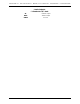
33
Not availible on revision 1.0 motherboards
34
Not availible on revision 1.0 motherboards
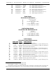
35
Use extreme caution when making discrete wire connections to the AUX. Power, as five pin 180¡
DIN connectors are numbered 3, 5, 2, 4, 1 as you face the socket on the back of the card cage.