
Manual
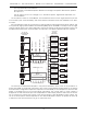

SIGNAL NAME COLOR SIGNAL FUNCTION
PIN #1 Ground 1 BROWN #1 Ground
PIN #9 + Input 1 RED #1 Balanced Audio Line Level Positive (+)
PIN #2 - Input 1 ORANGE #1 Balanced Audio Line Level Negative (-)
PIN #10 Ground 2 YELLOW #2 Ground
PIN #3 + Input 2 GREEN #2 Balanced Audio Line Level Positive (+)
PIN #11 - Input 2 BLUE #2 Balanced Audio Line Level Negative (-)
PIN #4 Ground 3 VIOLET #3 Ground
PIN #12 + Input 3 GRAY #3 Balanced Audio Line Level Positive (+)
PIN #5 - Input 3 WHITE #3 Balanced Audio Line Level Negative (-)
PIN #13 Ground 4 BLACK #4 Ground
PIN #6 + Input 4 BROWN #4 Balanced Audio Line Level Positive (+)
PIN #14 - Input 4 RED #4 Balanced Audio Line Level Negative (-)
PIN #7 Ground ORANGE #AES/EBU Ground
PIN #15 + AES/EBU IN YELLOW #AES/EBU POSITIVE Input
PIN #8 - AES/EBU IN GREEN #AES/EBU NEGATIVE Input
This connection is not available on the AB-3000 AudioBrick.
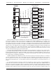
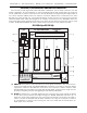
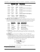
h) SMPTE Out/In, Status Out, AES/EBU Out: Nine position male DE-09 connector. There is one of
these connectors for each slot in the card cage. A CC-3004 has four for these connectors on
it, while the CC-3016 has sixteen. As can be seen by the functions carried on this connector,
it is used for all of the left over inputs and outputs on each of the DR-3000 and DR-4000s:
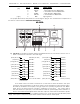
SIGNAL NAME COLOR SIGNAL FUNCTION
PIN #1 - SMPTE OUT BROWN SMPTE OUT Ground
PIN #2 - SMPTE IN ORANGE SMPTE IN Ground
PIN #3 Status #1 GREEN #1 Status Output
19
PIN #4 - AES/EBU VIOLET AES/EBU NEGATIVE Output
PIN #5 +5 v/Status #2 WHITE #2 Status Output
20
(+5 VDC on rev. 1.0)
PIN #6 + SMPTE OUT RED SMPTE OUT SIGNAL
PIN #7 + SMPTE IN YELLOW SMPTE IN SIGNAL
PIN #8 Status COMMON BLUE Status OUT COMMON
PIN #9 + AES/EBU GRAY AES/EBU POSITIVE Output
1 & 6 SMPTE Out: If enabled, The AB/DR-3000 can generate SMPTE time code as they play.
This is a line level output which can be attached to the inputs of most animation and
audio systems.
2 & 7 SMPTE In: This is the line level input for SMPTE time code to each AB/DR-3000.
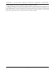
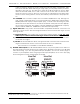
3, 8, & 5 Status Out: Status output #2 is not available on revision 1.0 card cages. These are
two optically isolated open collector outputs. They can be configured to go active when
a repeater is playing sound, at specific points while the repeater is playing, or, if operat-
ing from the Real Time Clock, once per second, minute, hour or every 24 hours. This lat-
ter mode is used to run ÔregulatorÕ style clock faces that require a ÔpulseÕ every minute,
and another each day to resynchronize all the attached clocks.
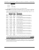
PIN #3
PIN #5
PIN #8
STATUS OUT #1
STATUS OUT #2
COMMON
+ 5 to 24 VDC SUPPLY
The two status outputs are fed directly from the a darlington output optoisolator. The
GILDERFLUKE & CO. ¥ 205 SOUTH FLOWER ST. ¥ BURBANK, CALIF. 91502-2102 ¥ 818/840-9484 ¥ FAX818/840-9485
21 of 92
19
Open collector switch to status common (pin #8)
20
Open collector switch to status common (pin #8)