
Manual

SIGNAL NAME:
Pin #1 Ground
Pin #2 N/C
Pin #3 + 5 VDC
Pin #4 - 12 to 15 VDC
Pin #5 + 12 to 15 VDC
This is the only power supply connection on the AB-3000 AudioBrick.
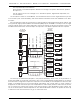
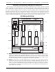
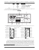
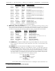
g) Audio Outputs: Twenty-five position female DB-25 connector. This is used for the balanced
audio outputs from the DR-3000 and DR-4000s installed in the card cage. CC-3004 Card
cages have one of these connectors on them. CC-3016 Card cages have four of these con-
nections on them. Each DR-3000 or DR-4000 has two balanced audio outputs on it. The
pinouts of these connectors is as follows:
SIGNAL NAME COLOR SIGNAL FUNCTION
PIN #1 Ground 1 BROWN right card #0 Ground
PIN #14 + Output 1 RED right card #0 Balanced Audio Line Level Positive (+)
PIN #2 - Output 1 ORANGE right card #0 Balanced Audio Line Level Negative (-)
PIN #15 Ground 2 YELLOW left card #0 Ground
PIN #3 + Output 2 GREEN left card #0 Balanced Audio Line Level Positive (+)
PIN #16 - Output 2 BLUE left card #0 Balanced Audio Line Level Negative (-)
PIN #4 Ground 3 VIOLET right card #1 Ground
PIN #17 + Output 3 GRAY right card #1 Balanced Audio Line Level Positive (+)
PIN #5 - Output 3 WHITE right card #1 Balanced Audio Line Level Negative (-)
PIN #18 Ground 4 BLACK left card #1 Ground
PIN #6 + Output 4 BROWN left card #1 Balanced Audio Line Level Positive (+)
PIN #19 - Output 4 RED left card #1 Balanced Audio Line Level Negative (-)
PIN #7 Ground 5 ORANGE right card #2 Ground
PIN #20 + Output 5 YELLOW right card #2 Balanced Audio Line Level Positive (+)
PIN #8 - Output 5 GREEN right card #2 Balanced Audio Line Level Negative (-)
PIN #21 Ground 6 BLUE left card #2 Ground
PIN #9 + Output 6 VIOLET left card #2 Balanced Audio Line Level Positive (+)
PIN #22 - Output 6 GRAY left card #2 Balanced Audio Line Level Negative (-)
PIN #10 Ground 7 WHITE right card #3 Ground
PIN #23 + Output 7 BLACK right card #3 Balanced Audio Line Level Positive (+)
PIN #11 - Output 7 BROWN right card #3 Balanced Audio Line Level Negative (-)
PIN #24 Ground 8 RED left card #3 Ground
PIN #12 + Output 8 ORANGE left card #3 Balanced Audio Line Level Positive (+)
PIN #25 - Output 8 YELLOW left card #3 Balanced Audio Line Level Negative (-)
PIN #13 N/C GREEN
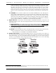
The balanced line drivers used on the DR-3000 and DR-4000s are a SSM-2142. This chip
provides a high quality balanced output that is compensated for 600 ohm lines. If operating
in single ended mode, the unused outputs must be tied to their respective ground lines. If
you donÕt, the output will be excessively noisy.
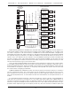
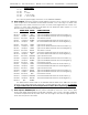
i) Audio Inputs & AES/EBU Inputs: Fifteen position male DB-15 connector. This is used to feed
analog and digital audio signals into a DR-4000 installed in slot 0 of the card cage. Additional
connectors may be wired to any other slots in the card cage if more than a single DR-4000 is
to be used. The pinout is as follows:
GILDERFLUKE & CO. ¥ 205 SOUTH FLOWER ST. ¥ BURBANK, CALIF. 91502-2102 ¥ 818/840-9484 ¥ FAX818/840-9485
20 of 92