
Datasheet

1/ Auxillary contact rating - 2A, 24Vdc Resistive load, 100,000 cycles. Minimum current is 1mA, 5V. The auxiliary contact
is mechanically linked to the main power contacts
.
2
/ 50 Mohms after life.
3/ Contactor can o
p
erate u
p
to 125°C in s
p
ecial cases - contact GIGAVAC for details
.
S
p
ecification
s
Unit
s
S
p
ecification
s
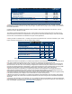
Contact Arrangement (main) Form X SPST-NO
Contact Arran
g
ement
(
Auxilar
y)
1/ Form A SPST-NO
Mechanical Life c
y
cle
s
1 millio
n
Contact Resistance
Max @ rated carry current
Typical @ rated carry current
mohms
mohms
.4
.15 to .3
Operate time, 2
5
˚C
Close (includes bounce) Max
Close (includes bounce) Typical
Bounce on close, Max
Release time (includes arc time at max. break current)
ms
ms
ms
ms
20
13
7
12
Insulation Resistance Mohm
s
100 2/
Dielectric at sea level
(
leaka
g
e < 1mA
)
VRM
S
2,50
0
Shock G’s peak 20
Vibration, Sinusoidal
(
50
0
-2000 Hz
p
eak
)
G’s 1
5
Operating ambient Temp Range
˚C
-55 to +85 3/
Storage ambient Temp Range
˚C
-70 to +175
Wei
g
ht, T
yp
ical K
g
(
Lb
)
0.50/
(
1.1
)
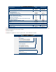
GX14 B C
A
Coil Voltage
B = 12 Vdc, internal coil suppression
C = 24 Vdc, internal coil suppression
F = 48 Vdc, internal coil suppression
Coil Termination
A = Flying leads, 38 cm (15 in)
B = Flying leads, 61 cm (24 in)
C = Flying leads, 122 cm (48 in)
Auxiliary Contact (same length as coil wire selection)
Blank = None
B = SPST, Normally Open