
Datasheet


Ratings are at 25ºC. For specific values at other temperatures, please contact GIGAVAC.
1/ Because the contactor is operated by a coil that changes resistance with temperature, the maximum coil voltage will be
lower than indicated at temperatures above 25C, and higher than indicated at temperatures below 25C
.
2
/ Contactor has two coils. Both are used for pull-in, and then in approximately 75 milliseconds, one coil is electronically
removed from the coil drive circuit. The remaining coil supplies low continuous hold power sufficient for the contactor to
meet all of its specified performance specifications. This provides the lowest coil power possible without the use of PWM
electronics that have been known to cause EMI emissions and/or cros
s
-talk on your system control power.
3/ Because the contactor is operated by a coil that changes resistance with temperature, and because Nominal Coil
v
oltage has been assumed for the I
n
-Rush, Hold Current and Hold Power specifications, Current/Wattage will be lower
t
han indicated at temperatures above 25C and higher than indicated at temperatures below 25C
.
4
/ For Pick-up testing of contactors with dual coils, the voltage can not be ramped up slowly, but must be applied instantly
t
o at least the maximum pull-in voltage or current. Otherwise, the contactor will not pick-up.
5/ Because the contactor is operated by a coil that changes resistance with temperature, Pick-up Voltage, Hold Voltage,
and Drop Out Voltage will be lower than indicated at temperatures below 25C and higher than indicated at temperatures
above 25C
.
6/ These DC coils have built-in coil suppression. The use of additional external coil suppression can slow the release time
and invalidate the life cycle ratings, or can cause the contactor not to be able to interrupt the maximum current specified. If
lower coil back EMF is re
q
uired,
p
lease contact GIGAVA
C
for assistance
.
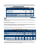
Nominal Coil Volta
g
e 12Vd
c
24Vd
c
Coil P/N Designation S T
Coil Voltage (Max) 1/ 1
5
3
0
In-Rush Current Max
(
75 ms
)
–
A
m
p
s 2/ 3/ 1.
8
0.
9
Hold Current after in-rush (Avg.) -
A
mps 3/ 0.090 0.045
Hold Power after in-rush
(
Av
g
.
)
–
Watts 3/ 1.
1
1.
1
Pick-up, Volts, Max 2/ 4/ 5/ 9 15
Hold, Volts, Min 5/ 5 1
0
Dro
p
-Out, Volts, Min 5/ 1.
0
1.
5
Coil Back EMF (volts) 6/ 45 45
S
p
ecification
s
Unit
s
S
p
ecification
s
Contact Arrangement (main) Form X SPST-NO
Contact Arran
g
ement
(
Auxilar
y)
1/ Form A SPST-NO
Mechanical Life cycles 1 million
Contact Resistance
Max @ rated carry current
Typical @ rated carry current
mohms
mohms
.4
.15 to .3
Operate time, 2
5
˚C
Close (includes bounce) Max
Close (includes bounce) Typical
Bounce on close, Max
Release time (includes arc time at max. break current)
ms
ms
ms
ms
20
13
7
12
Insulation Resistance Mohm
s
100 2/
Dielectric at sea level (leakage < 1mA) VRMS 2,500
Shock G’s pea
k
2
0
Vibration, Sinusoidal
(
50
0
-2000 Hz
p
eak
)
G’s 1
5
Operating ambient Temp Range
˚C
-55 to +85 3/
Storage ambient Temp Range ˚C -70 to +175
Wei
g
ht, T
yp
ical K
g
(
Lb
)
0.50/
(
1.1
)