
Datasheet


2
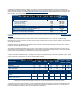
/ Assumes UL508 ratings with 4/0 cables, at a lower 50°C UL508 ambient temperature, and max. UL508 terminal
t
emperature rise of 50°C. For loads of 225A and below and the life cycle rating shown is longer than you need, you may
w
ant to consider the lesser priced GIGAVAC GX11 EPIC® sealed contactor. Smaller sized cables can be used at the
lower currents - see UL specifications for recommended cable sizes.
If your application requires a higher current rating, you may want to consider the GIGAVAC 350 Amp GX14 EPIC
®
sealed
contacto
r
.
1/ Assumes UL508 ratings with 4/0 cables, ambient max. UL508 temperature of 75°C, and max. UL508 terminal
t
emperature rise of 50°C. Contactor can also carry the higher currents shown on page 2 at 50°C ambient, and meet all of
t
he UL508 requirements
.
Contactor meets all of its published specifications at 85°C ambient, but terminal temperature can rise to 60°C, which is
higher than the 50°C allowed by UL508
.
T
he maximum terminal temperature rating is 175°C, which means much higher currents than shown on page 2 can be
carried and switched. However, this temperature is much higher than most cable insulation ratings, which mean busbars
must be used. Contact GIGAVAC for assistance for higher current applications.
2
/ Rating consists of combined inrush + cranking current at the times specified, with 2 seconds off between cycles. This is
higher current than is required for UL1107 for marine battery switche
s
.
75°C / 50°C
Cable size 1/
4 / 0
Continuous, UL508 Ma
x
1/
10 seconds (1 time)
100 Seconds (1 time)
300 Seconds
(
1 time
)
A
mp
Amp
Amp
Am
p
225 / 27
5
560 / 680
360 / 480
300 / 40
0
Starter Carry
–
Inrush 250 ms (10 repeats 1/ 2/) Amp NA / 2,000
Starter Carr
y
-Crankin
g
10 sec
(
10 re
p
eats 1/ 2/
)
Am
p
NA / 60
0
Maximum terminal Tem
p
, Continuou
s
De
g
C
17
5
Maximum terminal Temp, Intermittent Deg C 225
Ratings are at worse case temperature extremes, except coil resistance and current are at 25ºC.
1/ DC coils have built-in coil suppression. The use of additional external coil suppression can slow the release time and
invalidate the life cycle ratings, or can cause the contactor not to be able to interrupt the maximum current specified. If
lower coil back EMF is required, please contact GIGAVAC for assistance
.
Nominal Volt
s
12Vd
c
24Vd
c
48Vd
c
72Vd
c
120Vd
c
120Vac,
50/60Hz
240Vac,
50/60Hz
Coil P/N Desi
g
nation B C F H J K L
Max Volt
s
14 28 56 84 140 140 280
Pick-u
p
, Volts, Ma
x
7.
5
1
5
2
8
4
6
7
2
8
0
14
4
Hold, Volts, Min 4 9 1
8
2
8
4
6
4
6
9
2
Drop-Out, Volts, Min 0.5 0.5 1.8 2.7 4.5 4.5 9
Coil Resistance
@
2
5
ºC
(
Ohms ±10%
)
1
7
8
5
33
5
85
0
212
5
N/A N/A
Coil Current, mA, Max at nominal
V
olta
g
e
700 280 150 90 56 56 28
Coil Back EMF (volts)
- Built in suppression 1/
55 55 70 100 150 N/A N/A