Z690 AORUS ELITE AX Z690 AORUS ELITE Z690 A ELITE AX DDR4 (Z690 AORUS ELITE AX DDR4) Z690 AORUS ELITE DDR4 User's Manual Rev. 1002 12ME-Z69ELW4-1002R Z690 AORUS ELITE AX Z690 AORUS ELITE Z690 A ELITE AX Z690 AORUS DDR4 ELITE DDR4 For more product details, please visit GIGABYTE's website. To reduce the impacts on global warming, the packaging materials of this product are recyclable and reusable. GIGABYTE works with you to protect the environment.
Copyright © 2021 GIGA-BYTE TECHNOLOGY CO., LTD. All rights reserved. The trademarks mentioned in this manual are legally registered to their respective owners. Disclaimer Information in this manual is protected by copyright laws and is the property of GIGABYTE. Changes to the specifications and features in this manual may be made by GIGABYTE without prior notice.
Table of Contents Chapter 1 Product Introduction........................................................................................4 1-1 1-2 1-3 Motherboard Layout.......................................................................................... 4 Motherboard Block Diagram............................................................................. 6 Box Contents.....................................................................................................
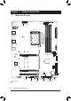
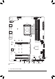
Chapter 1 1-1 Product Introduction Motherboard Layout ATX_12V_2X4 USB20 CPU_OPT D_LED2 CPU_FAN ATX_12V_2X2 LED_C2 ATX USB 2.0 Hub M2_WIFIj LGA1700 U32 U320G U32_LAN 80 60 110 80 60 M2P_SB Intel® Z690 M2M_SB iTE® Super I/O CODEC PCIEX4_1 USB 2.0 Hub PCIEX4_2 F_AUDIO THB_C2 THB_C1 3 5 7 SATA3 2 4 6 110 M_BIOS SYS_FAN2 D_LED1 F_USB2 SPI_TPM QFLASH_PLUS F_USB1 j Only for Z690 AORUS ELITE AX.
ATX_12V_2X4 USB20 CPU_OPT D_LED2 CPU_FAN ATX_12V_2X2 LED_C2 ATX USB 2.0 Hub DP_HDMI20 U32 U320G U32_LAN F_U32 Z690 A ELITE AX DDR4 Z690 AORUS ELITE DDR4 LGA1700 U32G2 80 60 110 80 60 M2P_SB Intel® Z690 M2M_SB iTE® Super I/O CODEC PCIEX4_1 USB 2.0 Hub PCIEX4_2 F_AUDIO THB_C2 THB_C1 3 5 7 SATA3 2 4 6 110 M_BIOS SYS_FAN2 D_LED1 F_USB2 SPI_TPM QFLASH_PLUS F_USB1 l Only for Z690 A ELITE AX DDR4.
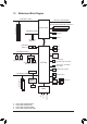
1-2 Motherboard Block Diagram PCI Express 5.0 Bus CPU CLK+/- (80~800 MHz) x16 1 PCI Express x16 DDR5 4800/4000 MHzjk DDR4 3200/3000/2933/2666/2400/2133 MHzlm LGA1700 CPU PCI Express 4.0 Bus DDI DDI HDMI 2.0 DMI 4.0 1 M.2 Socket 3 (M2A_CPU) DisplayPort 4 SATA 6Gb/s (SATA3 4~7) BIOS SPI Bus TPM PCI Express 4.0 Bus eSPI iTE® Bus Super I/O Switch 2 M.2 Socket 3 (M2P_SB, M2Q_SB) or 1 M.2 Socket 3 2 SATA 6Gb/s (M2M_SB) (SATA3 2, 3) Intel® Z690 1 USB Type-C®, with USB 3.
1-3 Box Contents 55 Z690 AORUS ELITE AX, Z690 AORUS ELITE, Z690 A ELITE AX DDR4, or Z690 AORUS ELITE DDR4 motherboard 55 User's Manual 55 Quick Installation Guide 55 One antennajl 55 Two SATA cables 55 M.2 screws 55 One G Connector * The box contents above are for reference only and the actual items shall depend on the product package you obtain. The box contents are subject to change without notice. j Only for Z690 AORUS ELITE AX. l Only for Z690 A ELITE AX DDR4.
Chapter 2 2-1 Hardware Installation Installation Precautions The motherboard contains numerous delicate electronic circuits and components which can become damaged as a result of electrostatic discharge (ESD). Prior to installation, carefully read the user's manual and follow these procedures: •• Prior to installation, make sure the chassis is suitable for the motherboard. •• Prior to installation, do not remove or break motherboard S/N (Serial Number) sticker or warranty sticker provided by your dealer.
2-2 Product Specifications CPU LGA1700 socket: Support for 12th Generation Intel® Core™ i9 processors/Intel® Core™ i7 processors/Intel® Core™ i5 processors (Go to GIGABYTE's website for the latest CPU support list.
Storage Interface CPU: - 1 x M.2 connector (Socket 3, M key, type 2260/2280/22110 PCIe 4.0 x4/x2 SSD support) (M2A_CPU) Chipset: - 1 x M.2 connector (Socket 3, M key, type 2260/2280/22110 SATA and PCIe 4.0 x4/x2 SSD support) (M2M_SB) - 2 x M.2 connectors (Socket 3, M key, type 2260/2280/22110 PCIe 4.0 x4/x2 SSD support) (M2Q_SB/M2P_SB) - 6 x SATA 6Gb/s connectors Support for RAID 0, RAID 1, RAID 5, and RAID 10 * Refer to "2-7 Internal Connectors," for the installation notices for the M.
Back Panel Connectors I/O Controller iTE® I/O Controller Chip Hardware Monitor BIOS Unique Features 1 x USB Type-C® port, with USB 3.2 Gen 2x2 support 2 x USB 3.2 Gen 2 Type-A ports (red) 3 x USB 3.2 Gen 1 ports 4 x USB 2.0/1.
Bundled Software Operating System Norton® Internet Security (OEM version) Realtek® Gaming LAN Bandwidth Control Utility Form Factor ATX Form Factor; 30.5cm x 24.4cm Support for Windows 10 64-bit * GIGABYTE reserves the right to make any changes to the product specifications and product-related information without prior notice.
2-3 Installing the CPU and CPU Cooler Read the following guidelines before you begin to install the CPU: •• Make sure that the motherboard supports the CPU. (Go to GIGABYTE's website for the latest CPU support list.) •• Always turn off the computer and unplug the power cord from the power outlet before installing the CPU to prevent hardware damage. •• Locate the pin one of the CPU. The CPU cannot be inserted if oriented incorrectly.
B. Installing the CPU Follow the steps below to correctly install the CPU into the motherboard CPU socket. Finger Tab u j Gently press the CPU socket lever handle down and away from the socket. k Completely lift up the CPU socket locking lever. l Use the finger tab on the side of the metal load plate to lift open the metal load plate with the plastic protective cover attached to it. l k j v Pin One Hold the CPU with your fingers by the edges.
C. Installing the CPU Cooler Be sure to install the CPU cooler after installing the CPU. (Actual installation process may differ depending the CPU cooler to be used. Refer to the user's manual for your CPU cooler.) u Apply an even and thin layer of thermal grease on the surface of the installed CPU. j v k k Place the cooler atop the CPU, aligning the four push pins through the pin holes on the motherboard. Push down on the push pins diagonally.
2-4 Installing the Memory Read the following guidelines before you begin to install the memory: •• Make sure that the motherboard supports the memory. It is recommended that memory of the same capacity, brand, speed, and chips be used. (Go to GIGABYTE's website for the latest supported memory speeds and memory modules.) •• Always turn off the computer and unplug the power cord from the power outlet before installing the memory to prevent hardware damage. •• Memory modules have a foolproof design.
2-5 Installing an Expansion Card Read the following guidelines before you begin to install an expansion card: •• Make sure the motherboard supports the expansion card. Carefully read the manual that came with your expansion card. •• Always turn off the computer and unplug the power cord from the power outlet before installing an expansion card to prevent hardware damage. Follow the steps below to correctly install your expansion card in the expansion slot. 1.
2-6 Back Panel Connectors USB 2.0/1.1 Port The USB port supports the USB 2.0/1.1 specification. Use this port for USB devices. SMA Antenna Connectors (2T2R)jl Use this connector to connect an antenna. Tighten the antennas to the antenna connectors and then aim the antennas correctly for better signal reception. USB 3.2 Gen 2 Type-A Port (Red) The USB 3.2 Gen 2 port supports the USB 3.2 Gen 2 specification and is compatible to the USB 3.2 Gen 1 and USB 2.0 specification. Use this port for USB devices.
RJ-45 LAN Port The Gigabit Ethernet LAN port provides Internet connection at up to 2.5 Gbps data rate. The following describes the states of the LAN port LEDs. Speed LED Activity LED LAN Port Speed LED: State Orange Green Off Activity LED: Description 2.5 Gbps data rate 1 Gbps data rate 100 Mbps data rate State Blinking Off Description Data transmission or receiving is occurring No data transmission or receiving is occurring Line Out The line out jack. Mic In The Mic in jack.
2-7 Internal Connectors 1 6 3 8 7 2 14 10 13 22 10 17 10 10 9 20 18 12 8 7 16 15 19 21 4 5 11 1) ATX_12V_2X2/ATX_12V_2X4 12) F_AUDIO 2) ATX 13) F_U32C 3) CPU_FAN 14) F_U32 4) SYS_FAN1/2/3 15) F_USB1/F_USB2 5) SYS_FAN4_PUMP 16) SPI_TPM 6) CPU_OPT 17) THB_C1/THB_C2 7) LED_C1/LED_C2 18) CLR_CMOS 8) D_LED1/D_LED2 19) BAT 9) SATA3 2/3/4/5/6/7 20) RST_SW/RST 10) M2A_CPU/M2P_SB/M2Q_SB/M2M_SB 21) QFLASH_PLUS 11) F_PANEL 22) CPU/DRAM/VGA/BOOT Read the followin
1/2) ATX_12V_2X2/ATX_12V_2X4/ATX (2x2, 2x4, 12V Power Connectors and 2x12 Main Power Connector) With the use of the power connector, the power supply can supply enough stable power to all the components on the motherboard. Before connecting the power connector, first make sure the power supply is turned off and all devices are properly installed. The power connector possesses a foolproof design. Connect the power supply cable to the power connector in the correct orientation.
3/4) CPU_FAN/SYS_FAN1/2/3 (Fan Headers) All fan headers on this motherboard are 4-pin. Most fan headers possess a foolproof insertion design. When connecting a fan cable, be sure to connect it in the correct orientation (the black connector wire is the ground wire). The speed control function requires the use of a fan with fan speed control design. For optimum heat dissipation, it is recommended that a system fan be installed inside the chassis. 1 CPU_FAN 1 Pin No.
6) CPU_OPT (Water Cooling CPU Fan Header) The fan header is 4-pin and possesses a foolproof insertion design. Most fan headers possess a foolproof insertion design. When connecting a fan cable, be sure to connect it in the correct orientation (the black connector wire is the ground wire). The speed control function requires the use of a fan with fan speed control design. Pin No.
U F _ F F _3 _0 _0 _B S F_ S S_F The headers can be used to connect a standard 5050 addressable LED strip, with maximum power rating of 5A (5V) and maximum number of 1000 LEDs. _ B_ _ 1 S _ D_LED2 1 Definition V (5V) Data No Pin GND F_USB3 F Pin No. 1 2 3 4 S _ _ S F_ Connect your addressable LED strip to the header. The power pin (marked with a triangle on the plug) of the LED strip must be connected to Pin 1 of the addressable LED strip header.
_ _ F_USB3 _ F B 3 _ _ _B _ FF S _ _0 F_USB3 F _ _ _B _ _ F S _ _ 0_ 0 F 10) M2A_CPU/M2P_SB/M2Q_SB/M2M_SB (M.2 Socket 3 Connectors) _ F _ There are two types of M.2 SSDs: M.2 SATA SSDs and M.2 PCIe SSDs. Be sure to verify which type of M.2_ SSDs is supported by the M.2 socket you want to use. Please note that an M.2 PCIe SSD cannot _ S _ _ 0 drive. F be used to create a RAID set either with an M.
Installation Notices for the M.2 and SATA Connectors: The availability of the SATA connectors may be affected by the type of device installed in the M.2 sockets. The M2M_SB connector shares bandwidth with the SATA3 2, 3 connector. Refer to the following table for details. •• M2A_CPU/M2Q_SB/M2P_SB: Type of M.2 SSD Connector SATA3 2 SATA3 3 SATA3 4 SATA3 5 SATA3 6 SATA3 7 M.2 PCIe SSD a a a a a a No M.2 SSD Installed a a a a a a SATA3 2 SATA3 3 SATA3 4 SATA3 5 SATA3 6 SATA3 7 M.
11) F_PANEL (Front Panel Header) Connect the power switch, reset switch, speaker, chassis intrusion switch/sensor and system status indicator on the chassis to this header according to the pin assignments below. Note the positive and negative pins before connecting the cables.
F_USB3 F _0 _ _ _ _B 12) F_AUDIO (Front Panel Audio Header) _ F The front panel audio header supports High Definition audio (HD). You may connect your chassis front panel audio module to this header. Make sure the wire assignments of the module connector match the pin assignments of the motherboard header. Incorrect connection between the module connector and the motherboard header will make the device unable to work or even damage it.
F_ U F_ The header conforms to USB 3.2 Gen 1 and USB 2.0 specification and can provide two USB ports. For purchasing the optional 3.5" front panel that provides two USB 3.2 Gen 1 ports, please contact the local dealer. 10 Pin No. 11 12 13 14 15 16 17 18 19 20 SSTX1SSTX1+ GND D1D1+ NC Definition D2+ D2GND B SS SSTX2+ SSTX2GND SSRX2+ SSRX2VBUS No Pin 1 Definition VBUS SSRX1SSRX1+ G.QBOFM GND 1 _S S 1 2 3 11 Pin No.
U _ _ _ U _ B 3 F _ S S_ _ B F_USB3 F 16) SPI_TPM (Trusted Platform Module Header) You may connect an SPI TPM (Trusted Platform Module) to this header. _ U S _ _ _ _ U _ B 3 _ _B S _ 11 12 F 1 F F_USB3 2 _ _ S _ _ _B _ _S _ S F_ F Definition Data Output Power (3.3V) No Pin NC Data Input CLK Chip Select GND IRQ NC NC RST _ F _0 _0 F _ F _ _0 F B_ S S_F B Pin No.
18) CLR_CMOS (Clear CMOS Jumper) Use this jumper to clear the BIOS configuration and reset the CMOS values to factory defaults. To clear the CMOS values, use a metal object like a screwdriver to touch the two pins for a few seconds. Open: Normal Short: Clear CMOS Values •• Always turn off your computer and unplug the power cord from the power outlet before clearing the CMOS values.
20) RST_SW/RST (Reset Button/Reset Jumper) The reset button (RST_SW) allows users to quickly turn on/off the computer in an open-case environment when they want to change hardware components or conduct hardware testing. The reset jumper (RST) can connect to the reset switch on the chassis front panel. Press the reset switch to restart the computer if the computer freezes and fails to perform a normal restart. 1 RST RST_SW Pin No.
S _ _ 22) CPU/DRAM/VGA/BOOT (Status LEDs) The status LEDs show whether the CPU, memory, graphics card, and operating system are working properly after system power-on. If the CPU/DRAM/VGA LED is on, that means the corresponding device is not working normally; if the BOOT LED is on, that means you haven't entered the operating system yet.
Chapter 3 BIOS Setup BIOS (Basic Input and Output System) records hardware parameters of the system in the CMOS on the motherboard. Its major functions include conducting the Power-On Self-Test (POST) during system startup, saving system parameters and loading operating system, etc. BIOS includes a BIOS Setup program that allows the user to modify basic system configuration settings or to activate certain system features.
Startup Screen: The following startup Logo screen will appear when the computer boots. Function Keys Function Keys: : BIOS SETUP\Q-FLASH Press the key to enter BIOS Setup or to access the Q-Flash utility in BIOS Setup. : BOOT MENU Boot Menu allows you to set the first boot device without entering BIOS Setup. In Boot Menu, use the up arrow key or the down arrow key to select the first boot device, then press to accept. The system will boot from the device immediately.
Chapter 4 4-1 Installing the Operating System and Drivers Operating System Installation With the correct BIOS settings, you are ready to install the operating system. If you want to install an operating system on an M.2 PCIe SSD or a RAID volume, you need to install the Intel® RST VMD Controller driver first during the OS installation process.
4-2 Drivers Installation After you install the operating system, a dialog box will appear on the bottom-right corner of the desktop asking if you want to download and install the drivers and GIGABYTE applications via APP Center. Click Install to proceed with the installation. (In BIOS Setup, make sure Settings\IO Ports\APP Center Download & Install Configuration\APP Center Download & Install is set to Enabled.) When the End User License Agreement dialog box appears, press to install APP Center.
Chapter 5 5-1 Appendix Configuring a RAID Set RAID Levels Minimum Number of Hard Drives Array Capacity Fault Tolerance RAID 0 RAID 1 RAID 5 RAID 10 ≥2 2 ≥3 4 (Number of hard drives -1) * Size of the smallest drive Yes (Number of hard drives/2) * Size of the smallest drive Yes Number of hard drives * Size of the smallest drive No Size of the smallest drive Yes Before you begin, please prepare the following items: This motherboard supports RAID 0, RAID 1, RAID 5, and RAID 10.
Regulatory Notices United States of America, Federal Communications Commission Statement Supplier's Declaration of Conformity 47 CFR § 2.1077 Compliance Information Product Name: Motherboard Trade Name: GIGABYTE Model Number: Z690 AORUS ELITE AX/Z690 AORUS ELITE/Z690 A ELITE AX DDR4/Z690 AORUS ELITE DDR4 Responsible Party – U.S. Contact Information: G.B.T. Inc. Address: 17358 Railroad street, City Of Industry, CA91748 Tel.: 1-626-854-9338 Internet contact information: https://www.gigabyte.
Under Industry Canada regulations, this radio transmitter may only operate using an antenna of a type and maximum (or lesser) gain approved for the transmitter by Industry Canada. To reduce potential radio interference to other users, the antenna type and its gain should be chosen so that the equivalent isotropically radiated power (e.i.r.p.) is not more than that necessary for successful communication.
European Community Radio Equipment Directive Compliance Statement: This equipment complies with all the requirements and other relevant provisions of Radio Equipment Directive 2014/53/EU. This equipment is suitable for home and office use in all the European Community Member States and EFTA Member States. The low band 5.15 -5.35 GHz is for indoor use only.
- 42 -
- 43 -
Contact Us GIGA-BYTE TECHNOLOGY CO., LTD. Address: No.6, Baoqiang Rd., Xindian Dist., New Taipei City 231, Taiwan TEL: +886-2-8912-4000, FAX: +886-2-8912-4005 Tech. and Non-Tech. Support (Sales/Marketing) : https://esupport.gigabyte.com WEB address (English): https://www.gigabyte.com WEB address (Chinese): https://www.gigabyte.com/tw •• GIGABYTE eSupport To submit a technical or non-technical (Sales/Marketing) question, please link to: https://esupport.gigabyte.