Z390 AORUS ELITE User's Manual Rev. 1001 12ME-Z39ELT-1001R For more product details, please visit GIGABYTE's website. To reduce the impacts on global warming, the packaging materials of this product are recyclable and reusable. GIGABYTE works with you to protect the environment.
Motherboard Z390 AORUS ELITE Motherboard Z390 AORUS ELITE Aug. 24, 2018 Aug. 24, 2018 Copyright © 2018 GIGA-BYTE TECHNOLOGY CO., LTD. All rights reserved. The trademarks mentioned in this manual are legally registered to their respective owners. Disclaimer Information in this manual is protected by copyright laws and is the property of GIGABYTE. Changes to the specifications and features in this manual may be made by GIGABYTE without prior notice.
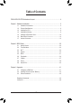
Table of Contents Z390 AORUS ELITE Motherboard Layout........................................................................4 Chapter 1 Hardware Installation......................................................................................5 1-1 1-2 1-3 1-4 1-5 1-6 1-7 Installation Precautions..................................................................................... 5 Product Specifications.......................................................................................
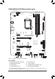
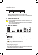
CPU_FAN SYS_FAN1_PUMP DDR4_A2 ATX_12V_2X4 DLED_V_SW2 LGA1151 HDMI R_USB30 LED_C2 CPU_OPT USB 2.0 Hub (Note) D_LED2 R_USB1 DDR4_A1 DDR4_B1 ATX_12V_2X2 DDR4_B2 Z390 AORUS ELITE Motherboard Layout ATX R_USB31 80 60 42 M2A 110 PCIEX1_1 Intel® GbE LAN Z390 AORUS ELITE PCIEX16 F_USB30C AUDIO F_USB30 USB30_LAN 80 60 Intel® Z390 42 SATA3 M2M iTE® Super I/O 5 3 1 4 2 0 PCIEX1_2 PCIEX4 PCIEX1_3 THB_C CODEC BAT B_BIOS PCIEX1_4 F_AUDIO SPDIF_O DLED_V_SW1 USB 2.
Chapter 1 1-1 Hardware Installation Installation Precautions The motherboard contains numerous delicate electronic circuits and components which can become damaged as a result of electrostatic discharge (ESD). Prior to installation, carefully read the user's manual and follow these procedures: •• Prior to installation, make sure the chassis is suitable for the motherboard. •• Prior to installation, do not remove or break motherboard S/N (Serial Number) sticker or warranty sticker provided by your dealer.
1-2 Product Specifications CPU Support for Intel 9000 processors and 8th Generation Intel® Core™ i7 processors/ Intel® Core™ i5 processors/Intel® Core™ i3 processors/Intel® Pentium® processors/ Intel® Celeron® processors in the LGA1151 package (Go to GIGABYTE's website for the latest CPU support list.
USB Internal Connectors Back Panel Connectors Chipset: - 2 x USB 3.1 Gen 2 Type-A ports (red) on the back panel - 1 x USB Type-C™ port with USB 3.1 Gen 1 support, available through the internal USB header - 6 x USB 3.1 Gen 1 ports (4 ports on the back panel, 2 ports available through the internal USB header) Chipset+2 USB 2.0 Hubs: - 8 x USB 2.0/1.
BIOS Unique Features Bundled Software 2 x 128 Mbit flash Use of licensed AMI UEFI BIOS Support for DualBIOS™ PnP 1.0a, DMI 2.7, WfM 2.0, SM BIOS 2.7, ACPI 5.0 Support for APP Center * Available applications in APP Center may vary by motherboard model. Supported functions of each application may also vary depending on motherboard specifications.
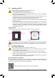
1-3 Installing the CPU Read the following guidelines before you begin to install the CPU: •• Make sure that the motherboard supports the CPU. (Go to GIGABYTE's website for the latest CPU support list.) •• Always turn off the computer and unplug the power cord from the power outlet before installing the CPU to prevent hardware damage. •• Locate the pin one of the CPU. The CPU cannot be inserted if oriented incorrectly.
The four memory sockets are divided into two channels and each channel has two memory sockets as following: Channel A: DDR4_A1, DDR4_A2 Channel B: DDR4_B1, DDR4_B2 Dual Channel Memory Configurations Table DDR4_B1 -DS/SS DS/SS Two Modules Four Modules DDR4_B2 DS/SS -DS/SS DDR4_A1 -DS/SS DS/SS DDR4_A2 DS/SS -DS/SS (SS=Single-Sided, DS=Double-Sided, "- -"=No Memory) Due to CPU limitations, read the following guidelines before installing the memory in Dual Channel mode. 1.
RJ-45 LAN Port The Gigabit Ethernet LAN port provides Internet connection at up to 1 Gbps data rate. The following describes the states of the LAN port LEDs.
1-7 Internal Connectors 6 1 2 5 4 11 9 10 3 16 7 15 8 7 19 20 21 22 14 13 10 9 11 18 17 6 12 1) ATX_12V_2X2 12) F_PANEL 2) ATX_12V_2X4 13) F_AUDIO 3) ATX 14) SPDIF_O 4) CPU_FAN 15) F_USB30C 5) CPU_OPT 16) F_USB30 6) SYS_FAN1/2/3_PUMP 17) F_USB1/F_USB2 7) M2A/M2M 18) TPM 8) SATA3 0/1/2/3/4/5 19) THB_C 9) LED_C1/LED_C2 20) BAT 10) D_LED1/D_LED2 21) CLR_CMOS 11) DLED_V_SW1/DLED_V_SW2 22) CPU/DRAM/VGA/BOOT Read the following guidelines before connecting
1/2/3) ATX_12V_2X2/ATX_12V_2X4/ATX (2x2, 2x4, 12V Power Connectors and 2x12 Main Power Connector) With the use of the power connector, the power supply can supply enough stable power to all the components on the motherboard. Before connecting the power connector, first make sure the power supply is turned off and all devices are properly installed. The power connector possesses a foolproof design. Connect the power supply cable to the power connector in the correct orientation.
4) CPU_FAN (Fan Header) The fan header is 4-pin. Most fan headers possess a foolproof insertion design. When connecting a fan cable, be sure to connect it in the correct orientation (the black connector wire is the ground wire). The speed control function requires the use of a fan with fan speed control design. For optimum heat dissipation, it is recommended that a system fan be installed inside the chassis. 1 Pin No.
_ F _0 F 7) M2A/M2M (M.2 Socket 3 Connectors) The M.2 B S_connectors support M.2 SATA SSDs or M.2 PCIe SSDs and support RAID configuration. Please note thatBan M.2 PCIe SSD cannot be used to create a RAID set either with an M.2 SATA SSD or a SATA hard drive. To create a RAID array with an M.2 PCIe SSD, you must set up the configuration in UEFI BIOS mode. Refer to Chapter 3, "Configuring a RAID Set," for instructions on configuring a RAID array.
8) SATA3 0/1/2/3/4/5 (SATA 6Gb/s Connectors) The SATA connectors conform to SATA 6Gb/s standard and are compatible with SATA 3Gb/s and SATA 1.5Gb/s standard. Each SATA connector supports a single SATA device. The Intel® Chipset supports RAID 0, RAID 1, RAID 5, and RAID 10. Refer to Chapter 3, "Configuring a RAID Set," for instructions on configuring a RAID array. G.QBOFM SATA3 5 3 1 4 2 0 G.QBOFM 7 1 7 1 G.QBOFM Pin No. 1 2 3 4 5 6 7 Definition GND TXP TXN GND RXN RXP GND G.
_3 _0 _3 U 10) D_LED1/D_LED2 (Digital LED Strip Headers) The headers can be used to connect a standard 5050 digital LED strip, with maximum power rating of 5A (12V or 5V) and maximum number of 1000 LEDs. There are 12V and 5V digital LED strips. Be sure to verify the voltage requirements of your digital LED strip and set the DLED_V_SW1 and DLED_V_SW2 jumpers accordingly.
12) F_PANEL (Front Panel Header) Connect the power switch, reset switch, speaker, chassis intrusion switch/sensor and system status indicator on the chassis to this header according to the pin assignments below. Note the positive and negative pins before connecting the cables. Power Switch •• PLED/PWR_LED (Power LED, Yellow/Purple): Connects to the power status indicator System Status LED on the chassis front panel. The LED is on S0 On when the system is operating.
_ _ _B S _ _0 F _ F 14) SPDIF_O (S/PDIF Out Header) B This header supports digital S/PDIF Out and connects a S/PDIF digital audio cable (provided by expansion cards) for digital audio output from your motherboard to certain expansion cards like graphics cards and S F_ cards.
B S_ B _ B 17) F_USB1/F_USB2 (USB 2.0/1.1 Headers) The headers conform to USB 2.0/1.1 specification. Each USB header can provide two USB ports via an optional USB Sbracket. For purchasing the optional USB bracket, please contact the local dealer. B_ B 9 1 Pin No. 1 2 3 4 5 _ 2S 10 S_ _ B _ _ Definition Power (5V) Power (5V) USB DXUSB DYUSB DX+ Pin No. 6 7 8 9 10 S S Definition USB DY+ GND GND No Pin NC •• Do not plug the IEEE 1394 bracket (2x5-pin) cable into the USB 2.0/1.1 header.
S_ _ B S 3 B SS U S _ _ _ U _ B 3 20) BAT (Battery) The battery provides power to keep the values (such as BIOS configurations, date, and time information) F_USB3 F in the CMOS when the computer is turned off. Replace the battery when the battery voltage drops to a low level, or the CMOS values may not be accurate or may be lost. S F B_ You may_ clear the CMOS values by removing the battery: 1. Turn off your computer and unplug the power cord. 2.
Chapter 2 BIOS Setup BIOS (Basic Input and Output System) records hardware parameters of the system in the CMOS on the motherboard. Its major functions include conducting the Power-On Self-Test (POST) during system startup, saving system parameters and loading operating system, etc. BIOS includes a BIOS Setup program that allows the user to modify basic system configuration settings or to activate certain system features.
2-2 The Main Menu System Time Setup Menus Hardware Information Configuration Items Current Settings Quick Access Bar allows you to enter Easy Mode, select BIOS default language, configure fan settings, or enter Q-Flash.
2-3 M.I.T. Whether the system will work stably with the overclock/overvoltage settings you made is dependent on your overall system configurations. Incorrectly doing overclock/overvoltage may result in damage to CPU, chipset, or memory and reduce the useful life of these components. This page is for advanced users only and we recommend you not to alter the default settings to prevent system instability or other unexpected results. (Inadequately altering the settings may result in system's failure to boot.
&& FCLK Frequency for Early Power On Allows you to set the FCLK frequency. Options are: Normal(800Mhz), 1GHz, 400MHz. (Default: 1GHz) `` Advanced CPU Core Settings && CPU Clock Ratio, CPU Frequency, FCLK Frequency for Early Power On The settings above are synchronous to those under the same items on the Advanced Frequency Settings menu. && AVX Offset (Note) AVX offset is the negative offset of AVX ratio. && TJ-Max offset (Note) Allows you to fine-tune the TJ Max offset value.
&& Intel(R) Speed Shift Technology (Intel® Speed Shift Technology) (Note) Enables or disables Intel® Speed Shift Technology. Enabling this feature allows the processor to ramp up its operating frequency more quickly and then improves the system responsiveness. (Default: Disabled) && CPU Enhanced Halt (C1E) (Note) Enables or disables Intel® CPU Enhanced Halt (C1E) function, a CPU power-saving function in system halt state.
&& Hardware Prefetcher Allows you to determine whether to enable hardware prefetcher to prefetch data and instructions from the memory into the cache. (Default: Auto) && Adjacent Cache Line Prefetch Allows you to determine whether to enable the adjacent cache line prefetch mechanism that lets the processor retrieve the requested cache line as well as the subsequent cache line. (Default: Auto) && Extreme Memory Profile (X.M.P.
&& Memory Timing Mode Manual and Advanced Manual allows the Memory Multiplier Tweaker, Channel Interleaving, Rank Interleaving, and memory timing settings below to be configurable. Options are: Auto (default), Manual, Advanced Manual. && Profile DDR Voltage When using a non-XMP memory module or Extreme Memory Profile (X.M.P.) is set to Disabled, the value is displayed according to your memory specification. When Extreme Memory Profile (X.M.P.
&& CPU Vcore/CPU VCCSA/DRAM Channel A/B Voltage/+3.3V/+5V/+12V/CPU VAXG Displays the current system voltages. `` Miscellaneous Settings && Max Link Speed Allows you to set the operation mode of the PCI Express slots to Gen 1, Gen 2, or Gen 3. Actual operation mode is subject to the hardware specification of each slot. Auto lets the BIOS automatically configure this setting. (Default: Auto) && 3DMark01 Enhancement Allows you to determine whether to enhance some legacy benchmark performance.
2-4 System This section provides information on your motherboard model and BIOS version. You can also select the default language used by the BIOS and manually set the system time. && Access Level Displays the current access level depending on the type of password protection used. (If no password is set, the default will display as Administrator.) The Administrator level allows you to make changes to all BIOS settings; the User level only allows you to make changes to certain BIOS settings but not all.
2-5 BIOS && Bootup NumLock State Enables or disables Numlock feature on the numeric keypad of the keyboard after the POST. (Default: On) && Security Option Specifies whether a password is required every time the system boots, or only when you enter BIOS Setup. After configuring this item, set the password(s) under the Administrator Password/User Password item. Setup A password is only required for entering the BIOS Setup program.
&& SATA Support Last Boot HDD Only E xcept for the previous boot drive, all SATA devices are disabled before the OS boot process completes. (Default) All Sata Devices All SATA devices are functional in the operating system and during the POST. This item is configurable only when Fast Boot is set to Enabled or Ultra Fast. && VGA Support Allows you to select which type of operating system to boot. Auto Enables legacy option ROM only. EFI Driver Enables EFI option ROM.
&& Storage Boot Option Control Allows you to select whether to enable the UEFI or legacy option ROM for the storage device controller. Do not launch Disables option ROM. UEFI Enables UEFI option ROM only. (Default) Legacy Enables legacy option ROM only. This item is configurable only when CSM Support is set to Enabled.
2-6 Peripherals && PCIE Bifurcation Support Allows you to determine how the the bandwidth of the PCIEX16 slot is divided. Options: PCIE x16, PCIE x8/x8, PCIE x8/x4/x4. (Default: PCIE x16) && Initial Display Output Specifies the first initiation of the monitor display from the installed PCI Express graphics card or the onboard graphics. IGFX Sets the onboard graphics as the first display. PCIe 1 Slot Sets the graphics card on the PCIEX16 slot as the first display.
`` OffBoard SATA Controller Configuration Displays information on your M.2 PCIe SSD if installed. `` Trusted Computing Enables or disables Trusted Platform Module (TPM). `` Intel(R) Bios Guard Technology Enables or disables the Intel® BIOS Guard feature, which protects the BIOS from malicious attacks. `` USB Configuration && Legacy USB Support Allows USB keyboard/mouse to be used in MS-DOS.
&& Media detect count Allows you to set the number of times to check the presence of media. This item is configurable only when Network Stack is enabled. (Default: 1) `` NVMe Configuration Displays information on your M.2 NVME PCIe SSD if installed. `` SATA And RST Configuration && SATA Controller(s) Enables or disables the integrated SATA controllers.
2-7 Chipset && VT-d (Note) Enables or disables Intel® Virtualization Technology for Directed I/O. (Default: Enabled) && Internal Graphics Enables or disables the onboard graphics function. (Default: Auto) && DVMT Pre-Allocated Allows you to set the onboard graphics memory size. Options are: 32M~1024M. (Default: 64M) && DVMT Total Gfx Mem Allows you to allocate the DVMT memory size of the onboard graphics. Options are: 128M, 256M, MAX.
2-8 Power && Platform Power Management Enables or disables the Active State Power Management function (ASPM). (Default: Disabled) && PEG ASPM Allows you to configure the ASPM mode for the device connected to the CPU PEG bus. This item is configurable only when Platform Power Management is set to Enabled. (Default: Disabled) && PCH ASPM Allows you to configure the ASPM mode for the device connected to Chipset's PCI Express bus.
&& Resume by Alarm Determines whether to power on the system at a desired time. (Default: Disabled) If enabled, set the date and time as following: Wake up day: Turn on the system at a specific time on each day or on a specific day in a month. Wake up hour/minute/second: Set the time at which the system will be powered on automatically. Note: When using this function, avoid inadequate shutdown from the operating system or removal of the AC power, or the settings may not be effective.
2-9 Save & Exit && Save & Exit Setup Press on this item and select Yes. This saves the changes to the CMOS and exits the BIOS Setup program. Select No or press to return to the BIOS Setup Main Menu. && Exit Without Saving Press on this item and select Yes. This exits the BIOS Setup without saving the changes made in BIOS Setup to the CMOS. Select No or press to return to the BIOS Setup Main Menu.
Chapter 3 3-1 Appendix Configuring a RAID Set RAID Levels Minimum Number of Hard Drives Array Capacity Fault Tolerance RAID 0 RAID 1 ≥2 2 Number of hard drives * Size of the smallest drive No Size of the smallest drive Yes RAID 5 RAID 10 ≥3 4 (Number of hard (Number of hard drives -1) * Size of drives/2) * Size of the the smallest drive smallest drive Yes Yes Before you begin, please prepare the following items: •• At least two SATA hard drives or SSDs.
C-2. UEFI RAID Configuration Steps: 1. In BIOS Setup, go to BIOS and set CSM Support to Disabled. Save the changes and exit BIOS Setup. 2. After the system reboot, enter BIOS Setup again. Then enter the Peripherals\Intel(R) Rapid Storage Technology sub-menu. 3. On the Intel(R) Rapid Storage Technology menu, press on Create RAID Volume to enter the Create RAID Volume screen. Enter a volume name with 1~16 letters (letters cannot be special characters) under the Name item and press .
Installing the SATA RAID/AHCI Driver and Operating System With the correct BIOS settings, you are ready to install the operating system. Installing the Operating System As some operating systems already include SATA RAID/AHCI driver, you do not need to install separate RAID/ AHCI driver during the Windows installation process.
A-2: Installation in Intel RST Premium With Intel Optane System Acceleration mode If the SATA controller has been configured in Intel RST Premium With Intel Optane System Acceleration mode, please follow the steps below: 1. After system restarts, go to the BIOS Setup, make sure CSM Support under the BIOS menu is disabled. 2. Go to Peripherals\SATA And RST Configuration and make sure Use RST Legacy OROM is disabled.
3-3 Drivers Installation •• Before installing the drivers, first install the operating system. •• After installing the operating system, insert the motherboard driver disk into your optical drive. Click on the message "Tap to choose what happens with this disc" on the top-right corner of the screen and select "Run Run.exe." (Or go to My Computer, double-click the optical drive and execute the Run.exe program.
Regulatory Statements Regulatory Notices This document must not be copied without our written permission, and the contents there of must not be imparted to a third party nor be used for any unauthorized purpose. Contravention will be prosecuted. We believe that the information contained herein was accurate in all respects at the time of printing. GIGABYTE cannot, however, assume any responsibility for errors or omissions in this text.
FCC Notice (U.S.A. Only) This equipment has been tested and found to comply with the limits for a Class B digital device, pursuant to Part 15 of the FCC Rules. These limits are designed to provide reasonable protection against harmful interference in a residential installation. This equipment generates, uses, and can radiate radio frequency energy and, if not installed and used in accordance with the instructions, may cause harmful interference to radio communications.
Contact Us GIGA-BYTE TECHNOLOGY CO., LTD. Address: No.6, Baoqiang Rd., Xindian Dist., New Taipei City 231, Taiwan TEL: +886-2-8912-4000, FAX: +886-2-8912-4005 Tech. and Non-Tech. Support (Sales/Marketing) : https://esupport.gigabyte.com WEB address (English): https://www.gigabyte.com WEB address (Chinese): https://www.gigabyte.com/tw •• GIGABYTE eSupport To submit a technical or non-technical (Sales/Marketing) question, please link to: https://esupport.gigabyte.