
User Manual
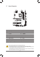
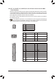
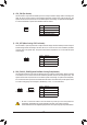
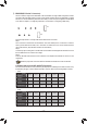
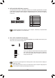
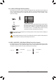
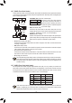
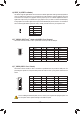
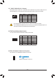
Table Of Contents

17) F_USB1/F_USB2 (USB 2.0/1.1 Headers)
TheheadersconformtoUSB2.0/1.1specication.EachUSBheadercanprovidetwoUSBportsviaan
optional USB bracket. For purchasing the optional USB bracket, please contact the local dealer.
Pin No. Denition Pin No. Denition
1 Power (5V) 6 USBDY+
2 Power (5V) 7 GND
3 USBDX- 8 GND
4 USBDY- 9 No Pin
5 USBDX+ 10 NC
• DonotplugtheIEEE1394bracket(2x5-pin)cableintotheUSB2.0/1.1header.
• Prior to installing the USB bracket, be sure to turn off your computer and unplug the power cord
from the power outlet to prevent damage to the USB bracket.
18) TPM (Trusted Platform Module Header)
You may connect a TPM (Trusted Platform Module) to this header.
11
1
F_USB30
F_U
B_
F_ F_
_
B
BS_
B
SB_
B
_S
S_
_
B
_U
_
B
S
123
123
123
123
1
1
1
1
BSS
S
_S
SSU
1 2 3
S3
BSSS
U
__ 3
F_USB3F
S _
S _
S _
SF
B_
B_
F
_0
S
S
_0F
_F
_
_
__B
U
S _S
_
SF_
B
USB0_B
B_
F_USB3
F_USB303
_
_3U
S_
Pin No. Denition Pin No. Denition
1 LAD0 7 LAD3
2 VCC3 8 GND
3 LAD1 9 LFRAME
4 No Pin 10 NC
5 LAD2 11 SERIRQ
6 LCLK 12 LRESET
12 2
19) THB_C (Thunderbolt
™
Add-in Card Connector)
This connector is for a GIGABYTE Thunderbolt
™
add-in card.
Supports a Thunderbolt
™
add-in card.
1
F_USB30
F_U
B_
F_ F_
_
B
BS_
B
SB_
B
_S
S_
_
B
_U
_
B
S
123
123
123
123
1
1
1
1
BSS
S
_S
SSU
1 2 3
S3
BSSS
U
__ 3
F_USB3F
S _
S _
S _
SF
B_
B_
F
_0
S
S
_0F
_F
_
_
__B
U
S _S
_
SF_
B
USB0_B
B_
F_USB3
F_USB303
_
_3U
S_
DEBUG
PORT
G.QBOFM
10
9
2
1
- 20 -