
User Manual
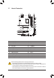
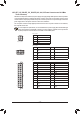
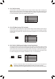
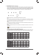
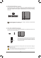
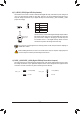
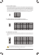
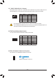
Table Of Contents

Pin No. Denition
1 V
2 D
3 No Pin
4 G
Before installing the devices, be sure to turn off the devices and your computer. Unplug the power
cord from the power outlet to prevent damage to the devices.
Forhowtoturnon/offthelightsoftheLEDstrippleasevisitthe"UniqueFeatures"webpageof
GIGABYTE's website.
10) D_LED1/D_LED2 (Digital LED Strip Headers)
Theheaderscanbeusedtoconnectastandard5050digitalLEDstrip,withmaximumpowerratingof5A
(12Vor5V)andmaximumnumberof1000LEDs.Thereare12Vand5VdigitalLEDstrips.Besureto
verifythevoltagerequirementsofyourdigitalLEDstripandsettheDLED_V_SW1andDLED_V_SW2
jumpers accordingly.
11) DLED_V_SW1/DLED_V_SW2 (Digital LED Strip Power Select Jumpers)
ThejumpersallowyoutoselectthesupplyvoltageoftheD_LED1andD_LED2headers.Besuretoverify
thevoltagerequirementsofyourdigitalLEDstripandsetthecorrectvoltagewiththesejumpersbefore
connection.IncorrectconnectionmayleadtothedamageoftheLEDstrip.
1-2:5V(Default)
2-3: 12V
1
1
DLED_V_SW1
1
1
DLED_V_SW2
1-2:5V(Default)
2-3: 12V
ConnectoneendoftheincludeddigitalLEDstripadaptercableto
thisheaderandtheotherendtoyourdigitalLEDstrip.Thepower
pin(marked with atriangle onthe plug) ofthe LEDstrip must
beconnected toPin 1ofthe digitalLED stripheader.Incorrect
connectionmayleadtothedamageoftheLEDstrip.
D_LED1 D_LED2
DigitalLEDStrip
Adapter Cable
1
F_USB30
F_U
B_
F_ F_
_
B
BS_
B
SB_
B
_S
S_
_
B
_U
_
B
S
123
123
123
123
1
1
1
1
BSS
S
_S
SSU
1 2 3
S3
BSSS
U
__ 3
F_USB3F
S _
S _
S _
SF
B_
B_
F
_0
S
S
_0F
_F
_
_
__B
U
S _S
_
SF_
B
USB0_B
B_
F_USB3
F_USB303
_
_3U
S_
1
F_USB30
F_U
B_
F_ F_
_
B
BS_
B
SB_
B
_S
S_
_
B
_U
_
B
S
123
123
123
123
1
1
1
1
BSS
S
_S
SSU
1 2 3
S3
BSSS
U
__ 3
F_USB3F
S _
S _
S _
SF
B_
B_
F
_0
S
S
_0F
_F
_
_
__B
U
S _S
_
SF_
B
USB0_B
B_
F_USB3
F_USB303
_
_3U
S_
1
- 17 -