
User Manual
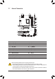
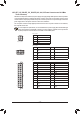
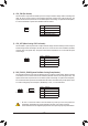
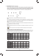
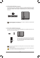
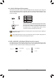
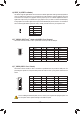
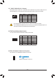
Table Of Contents

8) SATA3 0/1/2/3/4/5 (SATA 6Gb/s Connectors)
The SATA connectors conform to SATA 6Gb/s standard and are compatible with SATA 3Gb/s and SATA
1.5Gb/s standard. Each SATA connector supports a single SATA device. The Intel
®
ChipsetsupportsRAID0,
RAID1,RAID5,andRAID10.RefertoChapter3,"ConguringaRAIDSet,"forinstructionsonconguring
aRAIDarray.
Pin No. Denition
1 GND
2 TXP
3 TXN
4 GND
5 RXN
6 RXP
7 GND
To enable hot-plugging for the SATA ports, refer to Chapter 2, "BIOS Setup," "Peripherals\SATA
AndRSTConguration,"formoreinformation.
SATA3
5 3 1
4 2 0
1
1
7
7
DEBUG
PORT
G.QBOFM
DEBUG
PORT
G.QBOFM
DEBUG
PORT
G.QBOFM
9) LED_C1/LED_C2 (RGB LED Strip Headers)
Theheaderscanbeusedtoconnectastandard5050RGBLEDstrip(12V/G/R/B),withmaximumpower
rating of 2A (12V) and maximum length of 2m.
Pin No. Denition
1 12V
2 G
3 R
4 B
1
1
LED_C1
LED_C2
ConnectyourRGBLEDstriptotheheader.Thepowerpin(marked
withatriangleontheplug)oftheLEDstripmustbeconnectedto
Pin 1 (12V) of this header. Incorrect connection may lead to the
damageoftheLEDstrip.
Before installing the devices, be sure to turn off the devices and your computer. Unplug the power
cord from the power outlet to prevent damage to the devices.
Forhowtoturnon/offthelightsoftheLEDstrippleasevisitthe"UniqueFeatures"webpageof
GIGABYTE's website.
DEBUG
PORT
G.QBOFM
DEBUG
PORT
G.QBOFM
RGB
LEDStrip
1
12V
- 16 -