
User's Manual
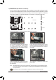
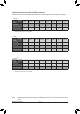
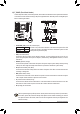

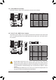
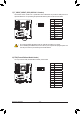
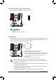

Table Of Contents
- Box Contents
- Optional Items
- X299X AORUS MASTER Motherboard Layout
- X299X AORUS MASTER Motherboard Block Diagram
- Chapter 1 Hardware Installation
- Chapter 2 BIOS Setup
- Chapter 3 Configuring a RAID Set
- Chapter 4 Drivers Installation
- Chapter 5 Unique Features
- Chapter 6 Appendix
- 36 -
Hardware Installation
F_USB30
F_U
B_
F_ F_
_
B
BS_
B
SB_
B
_S
S_
_
B
_U
_
B
S
123
123
123
123
1
1
1
1
BSS
S
_S
SSU
1 2 3 4 5
S3
BSSS
U
__ 3
F_USB3F
S _
S _
S _
SF
B_
B_
F
_0
S
S
_0F
_F
_
_
__B
U
S _S
_
SF_
B
USB0_B
B_
F_USB3
F_USB303
_
_3U
S_
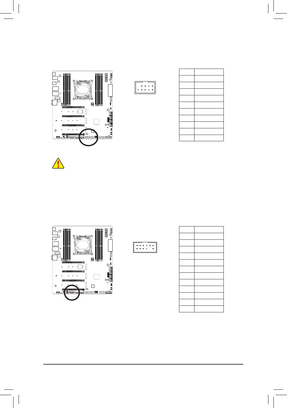
17) F_USB1/F_USB2/F_USB3 (USB 2.0/1.1 Headers)
TheheadersconformtoUSB2.0/1.1specication.EachUSBheadercanprovidetwoUSBportsviaan
optional USB bracket. For purchasing the optional USB bracket, please contact the local dealer.
Pin No. Denition
1 Power (5V)
2 Power (5V)
3 USB DX-
4 USB DY-
5 USB DX+
6 USB DY+
7 GND
8 GND
9 No Pin
10 NC
Pin No. Denition
1
LAD0
2
VCC3
3
LAD1
4
No Pin
5
LAD2
6
LCLK
7
LAD3
8
GND
9
LFRAME
10
NC
11
SERIRQ
12
LRESET
DEBUG
PORT
G.QBOFM
10
12
11
9
2
2
1
1
• Do not plug the IEEE 1394 bracket (2x5-pin) cable into the USB 2.0/1.1 header.
• Prior to installing the USB bracket, be sure to turn off your computer and unplug the power cord
from the power outlet to prevent damage to the USB bracket.
18) TPM (Trusted Platform Module Header)
You may connect a TPM (Trusted Platform Module) to this header.