
User's Manual
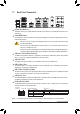
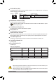
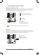
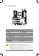
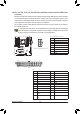
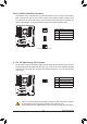
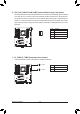
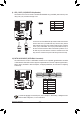
Table Of Contents
- Box Contents
- Optional Items
- X299X AORUS MASTER Motherboard Layout
- X299X AORUS MASTER Motherboard Block Diagram
- Chapter 1 Hardware Installation
- Chapter 2 BIOS Setup
- Chapter 3 Configuring a RAID Set
- Chapter 4 Drivers Installation
- Chapter 5 Unique Features
- Chapter 6 Appendix
- 30 -
Hardware Installation
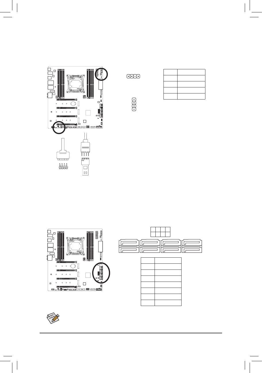
10) SATA3 0/1/2/3/4/5/6/7 (SATA 6Gb/s Connectors)
The SATA connectors conform to SATA 6Gb/s standard and are compatible with SATA 3Gb/s and SATA
1.5Gb/s standard. Each SATA connector supports a single SATA device. The Intel
®
Chipset supports RAID 0,
RAID 1, RAID 5, and RAID 10. Refer to Chapter 3, "Conguring a RAID Set," for instructions on conguring
a RAID array.
Pin No. Denition
1 GND
2 TXP
3 TXN
4 GND
5 RXN
6 RXP
7 GND
SATA3
7 5 3 1
6 4 2 0
To enable hot-plugging for the SATA ports, refer to Chapter 2, "BIOS Setup," "Settings\IO Ports\
SATA And RST Conguration," for more information.
1
1
7
DEBUG
PORT
G.QBOFM
DEBUG
PORT
G.QBOFM
DEBUG
PORT
G.QBOFM
DEBUG
PORT
G.QBOFM
7
9) LED_C1/LED_C2 (RGB LED Strip Headers)
The headers can be used to connect a standard 5050 RGB LED strip (12V/G/R/B), with maximum power
rating of 2A (12V) and maximum length of 2m.
Connect one end of the RGB LED strip extension cable to the header
and the other end to your RGB LED strip. The black wire (marked
with a triangle on the plug) of the extension cable must be connected
to Pin 1 (12V) of this header. The 12V pin (marked with an arrow) on
the other end of the extension cable must be lined up with the 12V of
the LED strip. Be careful with the connection orientation of the LED
strip; incorrect connection may lead to the damage of the LED strip.
12VRGB
BG12VR
12V
1
RGB LED
Strip
12VRGB
BG12VR
1
LED_C2
1
LED_C1
DEBUG
PORT
G.QBOFM
DEBUG
PORT
G.QBOFM
Pin No. Denition
1 12V
2 G
3 R
4 B