
User's Manual
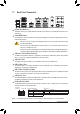
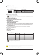
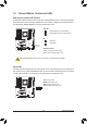
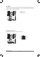
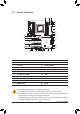
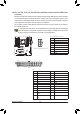
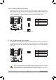
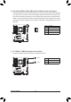
Table Of Contents
- Box Contents
- Optional Items
- X299X AORUS MASTER Motherboard Layout
- X299X AORUS MASTER Motherboard Block Diagram
- Chapter 1 Hardware Installation
- Chapter 2 BIOS Setup
- Chapter 3 Configuring a RAID Set
- Chapter 4 Drivers Installation
- Chapter 5 Unique Features
- Chapter 6 Appendix
- 29 -
Hardware Installation
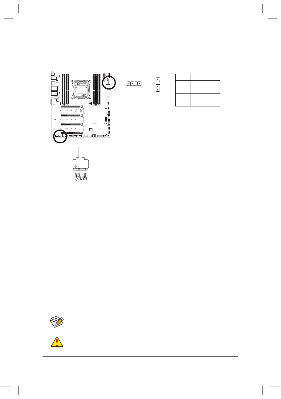
8) D_LED1/D_LED2 (Addressable LED Strip Headers)
The headers can be used to connect a standard 5050 addressable LED strip, with maximum power rating
of 5A (5V) and maximum number of 1000 LEDs.
Before installing the devices, be sure to turn off the devices and your computer. Unplug the power
cord from the power outlet to prevent damage to the devices.
For how to turn on/off the lights of the LED strip, refer to the instructions on in Chapter 5, "Unique
Features," "APP Center\RGB Fusion."
1
1
F_USB30
F_U
B_
F_ F_
_
B
BS_
B
SB_
B
_S
S_
_
B
_U
_
B
S
123
123
123
123
1
1
1
1
BSS
S
_S
SSU
1 2 3 4 5
S3
BSSS
U
__ 3
F_USB3F
S _
S _
S _
SF
B_
B_
F
_0
S
S
_0F
_F
_
_
__B
U
S _S
_
SF_
B
USB0_B
B_
F_USB3
F_USB303
_
_3U
S_
F_USB30
F_U
B_
F_ F_
_
B
BS_
B
SB_
B
_S
S_
_
B
_U
_
B
S
123
123
123
123
1
1
1
1
BSS
S
_S
SSU
1 2 3 4 5
S3
BSSS
U
__ 3
F_USB3F
S _
S _
S _
SF
B_
B_
F
_0
S
S
_0F
_F
_
_
__B
U
S _S
_
SF_
B
USB0_B
B_
F_USB3
F_USB303
_
_3U
S_
D_LED1
D_LED2
Pin No. Denition
1 V (5V)
2 D
3 No Pin
4 G
Connect one end of the included addressable LED strip adapter cable
to this header and the other end to your addressable LED strip. The
power pin (marked with a triangle on the plug) of the LED strip must
be connected to Pin 1 of the addressable LED strip header. Incorrect
connection may lead to the damage of the LED strip.
Addressable LED
Strip Adapter Cable
1