
User's Manual
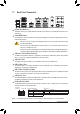
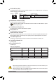
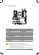
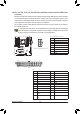
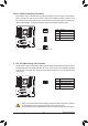
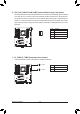
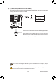
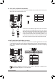
Table Of Contents
- Box Contents
- Optional Items
- X299X AORUS MASTER Motherboard Layout
- X299X AORUS MASTER Motherboard Block Diagram
- Chapter 1 Hardware Installation
- Chapter 2 BIOS Setup
- Chapter 3 Configuring a RAID Set
- Chapter 4 Drivers Installation
- Chapter 5 Unique Features
- Chapter 6 Appendix
- 28 -
Hardware Installation
6) SYS_FAN5_PUMP/SYS_FAN6_PUMP (System Fan/Water Cooling Pump Headers)
The fan/pump headers are 4-pin. Most fan headers possess a foolproof insertion design. When connecting
a fan cable, be sure to connect it in the correct orientation (the black connector wire is the ground wire).
The speed control function requires the use of a fan with fan speed control design. For optimum heat dis-
sipation, it is recommended that a system fan be installed inside the chassis. The header also provides
speed control for a water cooling pump, refer to Chapter 2, "BIOS Setup," "Settings\Smart Fan 5," for more
information.
DEBUG
PORT
G.QBOFM
Pin No. Denition
1 GND
2 Voltage Speed Control
3 Sense
4 PWM Speed Control
1
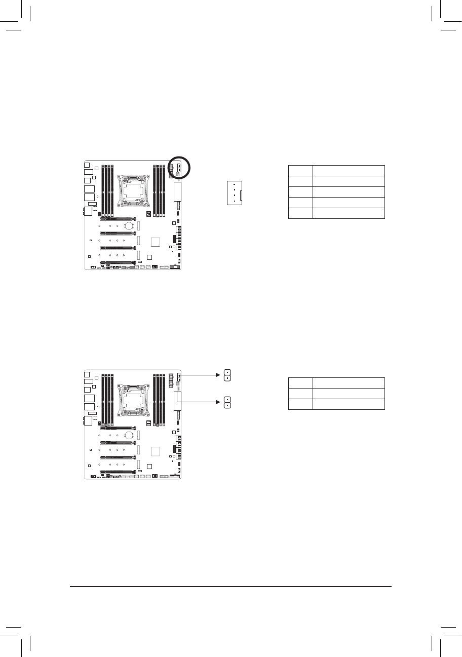
7) EC_TEMP1/EC_TEMP2 (Temperature Sensor Headers)
Connect the thermistors cables to the headers for temperature detection.
Pin No. Denition
1 SENSOR IN
2 GND
1
1
EC_TEMP2
EC_TEMP1