
User's Manual
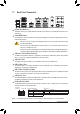
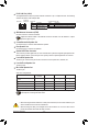
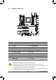
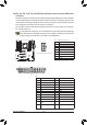
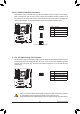
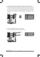
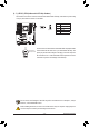
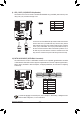
Table Of Contents
- Box Contents
- Optional Items
- X299X AORUS MASTER Motherboard Layout
- X299X AORUS MASTER Motherboard Block Diagram
- Chapter 1 Hardware Installation
- Chapter 2 BIOS Setup
- Chapter 3 Configuring a RAID Set
- Chapter 4 Drivers Installation
- Chapter 5 Unique Features
- Chapter 6 Appendix
- 22 -
Hardware Installation
SMA Antenna Connectors (2T2R)
Use this connector to connect an antenna.
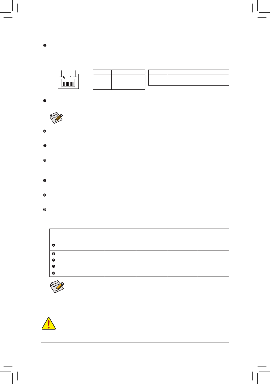
RJ-45 LAN Port (LAN1)
The Gigabit Ethernet LAN port provides Internet connection at up to 5 Gbps data rate. The following
describes the states of the LAN port LEDs.
Speed LED
Connection/
Activity LED
LAN Port
Speed LED:
State Description
Green 5 Gbps data rate
Orange 2.5 Gbps/ 1 Gbps/
100 Mbps data rate
Connection/Activity LED:
State Description
Blinking Data transmission or receiving is occurring
On No data transmission or receiving is occurring
Tighten the antenna cables to the antenna connectors and then move the antenna to a place
where the signal is good.
Center/Subwoofer Speaker Out
Use this audio jack to connect center/subwoofer speakers.
Rear Speaker Out
Use this audio jack to connect rear speakers.
Optical S/PDIF Out Connector
This connector provides digital audio out to an external audio system that supports digital optical audio.
Before using this feature, ensure that your audio system provides an optical digital audio in connector.
Line In/Side Speaker Out
The line in jack. Use this audio jack for line in devices such as an optical drive, walkman, etc.
Line Out/Front Speaker Out
The line out jack.
Mic In/Side Speaker Out
The Mic in jack.
AudioJackCongurations:
Jack
Headphone/
2-channel
4-channel 5.1-channel 7.1-channel
Center/Subwoofer Speaker
Out
a a
Rear Speaker Out
a a a
Line In/Side Speaker Out
a
Line Out/Front Speaker Out
a a a a
Mic In/Side Speaker Out
a
If you want to install a Side Speaker, you need to retask either the Line in or Mic in jack to be
Side Speaker out through the audio driver.
• Whenremovingthecableconnectedtoabackpanelconnector,rstremovethecablefromyour
device and then remove it from the motherboard.
• When removing the cable, pull it straight out from the connector. Do not rock it side to side to
prevent an electrical short inside the cable connector.