
User's Manual
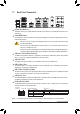
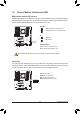
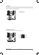
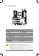
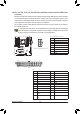
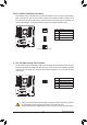
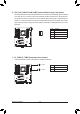
Table Of Contents
- Box Contents
- Optional Items
- X299X AORUS MASTER Motherboard Layout
- X299X AORUS MASTER Motherboard Block Diagram
- Chapter 1 Hardware Installation
- Chapter 2 BIOS Setup
- Chapter 3 Configuring a RAID Set
- Chapter 4 Drivers Installation
- Chapter 5 Unique Features
- Chapter 6 Appendix
- 21 -
Hardware Installation
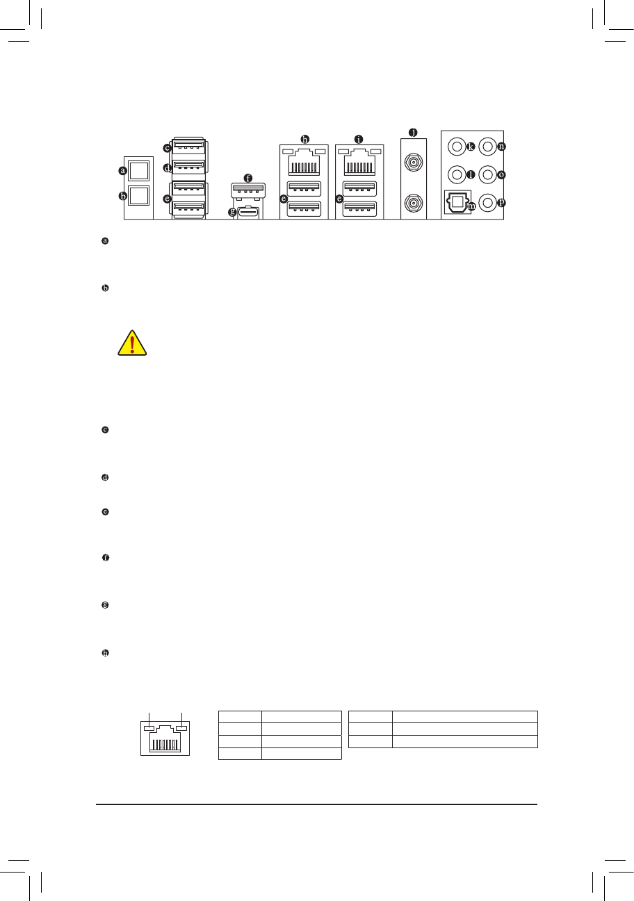
1-7 Back Panel Connectors
Q-Flash Plus Button
(Note)
This button allows you to update the BIOS when the power connector is connected but the system is not
powered on.
Clear CMOS Button
Use this button to clear the CMOS values (e.g. BIOS conguration) and reset the CMOS values to factory
defaults when needed.
USB 2.0/1.1 Port (Q-Flash Plus Port)
The USB port supports the USB 2.0/1.1 specication. Use this port for USB devices. Before using Q-Flash
Plus
(Note)
, make sure to insert the USB ash drive into this port rst.
USB 2.0/1.1 Port
The USB port supports the USB 2.0/1.1 specication. Use this port for USB devices.
USB 3.2 Gen 1 Port
The USB 3.2 Gen 1 port supports the USB 3.2 Gen 1 specication and is compatible to the USB 2.0
specication. Use this port for USB devices.
USB 3.2 Gen 2 Type-A Port (Red)
The USB 3.2 Gen 2 Type-A port supports the USB 3.2 Gen 2 specication and is compatible to the USB
3.2 Gen 1 and USB 2.0 specication. Use this port for USB devices.
USB Type-C
™
Port
The reversible USB port supports the USB 3.2 Gen 2 specication and is compatible to the USB 3.2 Gen 1
and USB 2.0 specication. Use this port for USB devices.
RJ-45 LAN Port (LAN2)
The Gigabit Ethernet LAN port provides Internet connection at up to 1 Gbps data rate. The following
describes the states of the LAN port LEDs.
• Always turn off your computer and unplug the power cord from the power outlet before using
the clear CMOS button.
• Do not use the clear CMOS button when the system is on, or the system may shutdown and
data loss or damage may occur.
• After system restart, go to BIOS Setup to load factory defaults (select Load Optimized Defaults) or
manually congure the BIOS settings (refer to Chapter 2, "BIOS Setup," for BIOS congurations).
(Note) To enable Q-Flash Plus function, refer to Chapter 5, "Unique Features," for more information.
Activity LED
Connection/
Speed LED
LAN Port
Activity LED:Connection/Speed LED:
State Description
Orange 1 Gbps data rate
Green 100 Mbps data rate
Off 10 Mbps data rate
State Description
Blinking Data transmission or receiving is occurring
On No data transmission or receiving is occurring