X299X AORUS MASTER User's Manual Rev. 1001 12ME-X29XAMR-1001R For more product details, please visit GIGABYTE's website. To reduce the impacts on global warming, the packaging materials of this product are recyclable and reusable. GIGABYTE works with you to protect the environment.
Motherboard X299X AORUS MASTER Motherboard X299X AORUS MASTER Sept. 20, 2019 Sept.
Copyright © 2019 GIGA-BYTE TECHNOLOGY CO., LTD. All rights reserved. The trademarks mentioned in this manual are legally registered to their respective owners. Disclaimer Information in this manual is protected by copyright laws and is the property of GIGABYTE. Changes to the specifications and features in this manual may be made by GIGABYTE without prior notice.
Table of Contents Box Contents....................................................................................................................6 Optional Items..................................................................................................................6 X299X AORUS MASTER Motherboard Layout...............................................................7 X299X AORUS MASTER Motherboard Block Diagram..................................................8 Chapter 1 Hardware Installation.....
Chapter 4 Drivers Installation........................................................................................85 4-1 4-2 4-3 Drivers & Software.......................................................................................... 85 Application Software....................................................................................... 86 Information...................................................................................................... 86 Chapter 5 Unique Features............
Box Contents 55 55 55 55 55 55 55 55 55 55 55 55 55 X299X AORUS MASTER motherboard Motherboard driver disc User's Manual Quick Installation Guide Four SATA cables One Wi-Fi antenna One addressable LED strip adapter cable Two RGB LED strip extension cables One noise detection cable Two thermistor cables One G Connector M.2 screw(s)/M.2 standoff(s) Two Velcro Cable Ties The box contents above are for reference only and the actual items shall depend on the product package you obtain.
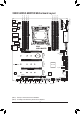
LED_C2 EC_TEMP2 EC_TEMP1 ATX U32_LAN2 U32_LAN1 X299X AORUS MASTER (Note 1) CPU_FAN F_U32C Aquantia 5GbE LAN AUDIO F_U32_2 M2_WIFI SYS_FAN1 Intel® GbE LAN (Note 1) CPU_OPT PCIEX16_1 80 60 7 5 3 1 6 4 2 0 60 SATA3 80 ASMedia® USB 3.2 Gen 2 Controller M2M 110 BAT CPU DRAM VGA BOOT ESS SABRE9218 110 M2P PCIEX8_1 42 Intel® X299 B_BIOS M_BIOS F_AUDIO 42 iTE® Super I/O USB 2.
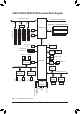
X299X AORUS MASTER Motherboard Block Diagram PCI Express 3.0 Bus CPU CLK+/- (100~500 MHz) x16 x16 x8 Switch DDR4 2933 (Note)/2666/2400/2133 MHz PCI Express x8_2 1 M.2 Socket 3 (M2M) 1 M.2 Socket 3 (M2Q) DMI 3.0 PCI Express x8_1 PCI Express x16_2 PCI Express x16_1 LGA2066 CPU 1 M.2 Socket 3 (M2P) SPI Bus 8 SATA 6Gb/s (SATA3 0~7) 2 USB 2.0/1.1 Dual BIOS LPC iTE® Bus Super I/O TPM 2 USB 3.2 Gen 1 8 USB 3.2 Gen 1 Realtek® USB 3.2 Gen 1 Hub x1 PCI Express 3.
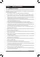
Chapter 1 1-1 Hardware Installation Installation Precautions The motherboard contains numerous delicate electronic circuits and components which can become damaged as a result of electrostatic discharge (ESD). Prior to installation, carefully read the user's manual and follow these procedures: •• Prior to installation, make sure the chassis is suitable for the motherboard. •• Prior to installation, do not remove or break motherboard S/N (Serial Number) sticker or warranty sticker provided by your dealer.
1-2 Product Specifications CPU S upport for Intel® Core™ i7-7800X and above X series processors/Intel® Core™ i9 X series processors in the LGA2066 package (Go to GIGABYTE's website for the latest CPU support list.
Multi-Graphics S upport for NVIDIA® Quad-GPU SLI™ and 2-Way NVIDIA® SLI™ technologies Technology Support for AMD Quad-GPU CrossFire™ and 2-Way AMD CrossFire™ technologies Storage Interface CPU: - 1 x M.2 connector (Socket 3, M key, type 2260/2280/22110 PCIe x4/x2 SSD support) (M2M) - 1 x M.2 connector (Socket 3, M key, type 2242/2260/2280/22110 PCIe x4/x2 SSD support) (M2Q) * The M2M and M2Q connectors become unavailable when an Intel® Core™ X series 28-lane processor is used.
Internal Connectors Back Panel Connectors 1 x front panel header 1 x front panel audio header 1 x USB Type-C™ port, with USB 3.2 Gen 2 support 2 x USB 3.2 Gen 1 headers 3 x USB 2.0/1.1 headers 1 x noise detection header 1 x Thunderbolt™ add-in card connector 1 x Trusted Platform Module (TPM) header (2x6 pin, for the GC-TPM2.
Unique Features Support for APP Center * Available applications in APP Center may vary by motherboard model. Supported functions of each application may also vary depending on motherboard specifications.
1-3 Installing the CPU and CPU Cooler Read the following guidelines before you begin to install the CPU: •• Make sure that the motherboard supports the CPU. (Go to GIGABYTE's website for the latest CPU support list.) •• Always turn off the computer and unplug the power cord from the power outlet before installing the CPU to prevent hardware damage. •• Locate the pin one of the CPU. The CPU cannot be inserted if oriented incorrectly.
B. Follow the steps below to correctly install the CPU into the motherboard CPU socket. •• Before installing the CPU, make sure to turn off the computer and unplug the power cord from the power outlet to prevent damage to the CPU. •• To protect the socket contacts, do not remove the protective plastic cover unless the CPU is inserted into the CPU socket. Save the cover properly and replace it if the CPU is removed.
1-3-2 Installing the CPU Cooler Refer to the steps below to correctly install the CPU cooler on the motherboard. (Actual installation process may differ depending the CPU cooler to be used. Refer to the user's manual for your CPU cooler.) Step 1: Apply an even and thin layer of thermal grease on the surface of the installed CPU. Step 2: Place the cooler atop the CPU, aligning the four mounting screws with the mounting holes on the ILM.
1-4 Installing the Memory Read the following guidelines before you begin to install the memory: •• Make sure that the motherboard supports the memory. It is recommended that memory of the same capacity, brand, speed, and chips be used. (Go to GIGABYTE's website for the latest supported memory speeds and memory modules.) •• Always turn off the computer and unplug the power cord from the power outlet before installing the memory to prevent hardware damage. •• Memory modules have a foolproof design.
1-4-2 Installing a Memory Before installing a memory module, make sure to turn off the computer and unplug the power cord from the power outlet to prevent damage to the memory module. DDR4 and DDR3 DIMMs are not compatible to each other or DDR2 DIMMs. Be sure to install DDR4 DIMMs on this motherboard. Notch DDR4 DIMM A DDR4 memory module has a notch, so it can only fit in one direction. Follow the steps below to correctly install your memory modules in the memory sockets.
1-5 Installing an Expansion Card Read the following guidelines before you begin to install an expansion card: •• Make sure the motherboard supports the expansion card. Carefully read the manual that came with your expansion card. •• Always turn off the computer and unplug the power cord from the power outlet before installing an expansion card to prevent hardware damage. PCI Express x16 Slot Follow the steps below to correctly install your expansion card in the expansion slot. 1.
1-6 Setting up AMD CrossFire™/NVIDIA® SLI™ Configuration A. System Requirements -- Windows 10 64-bit operating system -- A CrossFire/SLI-supported motherboard with two or more PCI Express x16 slots and correct driver -- CrossFire/SLI-ready graphics cards of identical brand and chip and correct driver -- CrossFire (Note)/SLI bridge connectors -- A power supply with sufficient power is recommended (Refer to the manual of your graphics cards for the power requirement) B.
1-7 Back Panel Connectors Q-Flash Plus Button (Note) This button allows you to update the BIOS when the power connector is connected but the system is not powered on. Clear CMOS Button Use this button to clear the CMOS values (e.g. BIOS configuration) and reset the CMOS values to factory defaults when needed. •• Always turn off your computer and unplug the power cord from the power outlet before using the clear CMOS button.
RJ-45 LAN Port (LAN1) The Gigabit Ethernet LAN port provides Internet connection at up to 5 Gbps data rate. The following describes the states of the LAN port LEDs. Speed LED Connection/ Activity LED Speed LED: Connection/Activity LED: State Green Orange Description 5 Gbps data rate 2.
_ _B _ _ 3 _ _ 1 2 3 1 2 3 3 _ S _ 1 2 3 S _S U 1 2 3 The BIOS switch (BIOS_SW) allows users to easily select a different BIOS for boot up or overclocking, helping to reduce BIOS failure during overclocking. The SB switch allows enabling or disabling of the Dual BIOS function. The LED indicator (MBIOS_LED/BBIOS_LED) shows which BIOS is active.
Quick Buttons This motherboard has 2 quick buttons: power button and reset button. The power button and reset button allow users to quickly turn on/off or reset the computer in an open-case environment when they want to change hardware components or conduct hardware testing. PW_SW: Power Button RST_SW: Reset Button RST_SW PW_SW Voltage Measurement Points Use a multimeter to measure the following motherboard voltages.
1-9 Internal Connectors 3 1 7 6 9 8 2 16 15 5 11 4 20 10 11 11 22 19 21 14 13 8 9 18 4 17 16 12 1) ATX_12V_2X4_1/ATX_12V_2X4_2 12) F_PANEL 2) ATX 13) F_AUDIO 3) CPU_FAN 14) NOISE_SENSOR 4) SYS_FAN1/2/3/4 15) F_U32C 5) CPU_OPT 16) F_U32_1/F_U32_2 6) SYS_FAN5_PUMP/SYS_FAN6_PUMP 17) F_USB1/F_USB2/F_USB3 7) EC_TEMP1/EC_TEMP2 18) TPM 8) D_LED1/D_LED2 19) THB_C 9) LED_C1/LED_C2 20) BAT 10) SATA3 0/1/2/3/4/5/6/7 21) CLR_CMOS 11) M2M/M2P/M2Q 22) VROC Read t
1/2) ATX_12V_2X4_1/ATX_12V_2X4_2/ATX (2x4 12V Power Connectors and 2x12 Main Power Connector) With the use of the power connector, the power supply can supply enough stable power to all the components on the motherboard. Before connecting the power connector, first make sure the power supply is turned off and all devices are properly installed. The power connector possesses a foolproof design. Connect the power supply cable to the power connector in the correct orientation.
3/4) CPU_FAN/SYS_FAN1/2/3/4 (Fan Headers) All fan headers on this motherboard are 4-pin. Most fan headers possess a foolproof insertion design. When connecting a fan cable, be sure to connect it in the correct orientation (the black connector wire is the ground wire). The speed control function requires the use of a fan with fan speed control design. For optimum heat dissipation, it is recommended that a system fan be installed inside the chassis. 1 CPU_FAN 1 SYS_FAN1 Pin No.
6) SYS_FAN5_PUMP/SYS_FAN6_PUMP (System Fan/Water Cooling Pump Headers) The fan/pump headers are 4-pin. Most fan headers possess a foolproof insertion design. When connecting a fan cable, be sure to connect it in the correct orientation (the black connector wire is the ground wire). The speed control function requires the use of a fan with fan speed control design. For optimum heat dissipation, it is recommended that a system fan be installed inside the chassis.
_3 _3 U 8) D_LED1/D_LED2 (Addressable LED Strip Headers) The headers can be used to connect a standard 5050 addressable LED strip, with maximum power rating of 5A (5V) and maximum number of 1000 LEDs. 1 D_LED1 F_USB30 3 _ F_USB3 F D_LED2 Definition V (5V) D No Pin G S F_ S _ B Pin No. 1 2 3 4 1 F F_USB3 Connect one end of the included addressable LED strip adapter cable to this header and the other end to your addressable LED strip.
9) LED_C1/LED_C2 (RGB LED Strip Headers) DEBUG The headers can be used to connect aPORT standard 5050 RGB LED strip (12V/G/R/B), with maximum power rating of 2A (12V) and maximum length of 2m. Pin No. 1 2 3 4 1 LED_C1 1 LED_C2 DEBUG PORT B R G 12V B R G 12V B R G 12V B R G 12V 1 12V RGB LED Strip Definition 12V G R B Connect one end of the RGB LED strip extension cable to the header and the other end to your RGB LED strip.
F_USB3 F _ _ _B _0 S _ F _0 _ F _ _B S F_ B _ S _ 11) M2M/M2P/M2Q (M.2 Socket 3 Connectors) The M.2 connectors support M.2 SATA SSDs or M.2 PCIe SSDs and support RAID configuration. Please _ F note that an M.2 PCIe SSD cannot be used to create a RAID set either with an M.2 SATA SSD or a SATA 0 up Fthe configuration in UEFI BIOS hard drive. To create a RAID array with an M.2 PCIe SSD, you must _set mode. Refer to Chapter 3, "Configuring a RAID Set," for instructions on configuring a RAID array.
Installation Notices for the M.2 and SATA Connectors: The M2P connector shares bandwidth with the SATA3 0 connector. Refer to the following tables for details. •• M2M (Note): Connector SATA3 0 SATA3 1 SATA3 2 SATA3 3 SATA3 4 SATA3 5 SATA3 6 SATA3 7 M.2 PCIe SSD * a a a a a a a a No M.2 SSD Installed a a a a a a a a Type of M.2 SSD a: Available, r: Not available * The M2M connector supports only PCIe SSDs. •• M2P: Type of M.
12) F_PANEL (Front Panel Header) Connect the power switch, reset switch, speaker, chassis intrusion switch/sensor and system status indicator on the chassis to this header according to the pin assignments below. Note the positive and negative pins before connecting the cables.
13) F_AUDIO (Front Panel Audio Header) The front panel audio header supports High Definition audio (HD). You may connect your chassis front panel audio module to this header. Make sure the wire assignments of the module connector match the pin assignments of the motherboard header. Incorrect connection between the module connector and the motherboard header will make the device unable to work or even damage it. 9 1 F_ F_ U 10 2 Pin No.
S F _3 U 15) F_U32C (USB 3.2 Gen 2 Header) Definition VBUS TX2+ TX2GND RX2+ RX2GND DD+ CC2 1 2 3 1 16) F_U32_1/F_U32_2 (USB 3.2 Gen 1 Headers) F_USB30 1 Pin No. 11 12 13 14 15 16 17 18 19 20 1 2 3 S 20 Definition VBUS TX1+ TX1GND RX1+ RX1VBUS CC1 SBU1 SBU2 1 2 3 1 Pin No. 1 2 3 4 5 6 7 8 9 10 S 11 1 F_ USB 0_ B 10 B SS F_USB30 3 1 F_USB3 1 2 3 F_ U 1 10 1 F_U32_1 10 F_U32_2 B SS Definition D2+ D2GND SSTX2+ SSTX2GND SSRX2+S SSRX2VBUS No Pin 1 Pin No.
1 B SS 17) F_USB1/F_USB2/F_USB3 (USB 2.0/1.1 Headers) 1 _S The headers conform to USB 2.0/1.1 specification. Each USB header can provide two USB ports via an optional USB bracket. For purchasing the optional USB bracket, please contact the local dealer. 1 1 _ B Pin No.
B SS 3 _ _ _ U _ B 3 F_USB3 F S F (Thunderbolt™ Add-in Card Connector) 19) THB_C _ This connector is for a GIGABYTE Thunderbolt™ add-in card. _ 1 _ _S S _ B_ S USB 0_ B B_ _ _B B_ F_USB30 3 F_USB3 Supports a Thunderbolt™ add-in card. _ S F_ B 20) BAT (Battery) The battery provides power to keep the values (such as BIOS configurations, date, and time information) B in the CMOS when the computer is turned off.
21) CLR_CMOS (Clear CMOS Jumper) Use this jumper to clear the BIOS configuration and reset the CMOS values to factory defaults. To clear the CMOS values, use a metal object like a screwdriver to touch the two pins for a few seconds. S S U S Open: Normal _ _ _ Short: Clear CMOS Values B_ B_ •• Always turn off your computer and unplug the power cord from the power outlet before clearing the CMOS values.
Chapter 2 BIOS Setup BIOS (Basic Input and Output System) records hardware parameters of the system in the CMOS on the motherboard. Its major functions include conducting the Power-On Self-Test (POST) during system startup, saving system parameters and loading operating system, etc. BIOS includes a BIOS Setup program that allows the user to modify basic system configuration settings or to activate certain system features.
2-1 Startup Screen The following startup Logo screen will appear when the computer boots. Function Keys Function Keys: : BIOS SETUP\Q-FLASH Press the key to enter BIOS Setup or to access the Q-Flash utility in BIOS Setup. : BOOT MENU Boot Menu allows you to set the first boot device without entering BIOS Setup. In Boot Menu, use the up arrow key or the down arrow key to select the first boot device, then press to accept.
2-2 The Main Menu Advanced Mode The Advanced Mode provides detailed BIOS settings. You can press the arrow keys on your keyboard to move among the items and press to accept or enter a sub-menu. Or you can use your mouse to select the item you want. (Sample BIOS Version: T62) System Time Setup Menus Configuration Items Hardware Information Option Description Current Settings Quick Access Bar allows you to quickly move to the General Help, Easy Mode, Smart Fan 5, or Q-Flash screen.
B. Easy Mode Easy Mode allows users to quickly view their current system information or to make adjustments for optimum performance. In Easy Mode, you can use your mouse to move through configuration items or press to switch to the Advanced Mode screen.
2-3 Favorites (F11) Set your frequently used options as your favorites and use the key to quickly switch to the page where all of your favorite options are located. To add or remove a favorite option, go to its original page and press on the option. The option is marked with a star sign if set as a "favorite.
2-4 Tweaker Whether the system will work stably with the overclock/overvoltage settings you made is dependent on your overall system configurations. Incorrectly doing overclock/overvoltage may result in damage to CPU, chipset, or memory and reduce the useful life of these components. This page is for advanced users only and we recommend you not to alter the default settings to prevent system instability or other unexpected results.
Advanced CPU Core Settings && CPU Over Temperature Protection(Tjmax) Allows you to fine-tune the TJ Max offset value. (Default: Auto) && CPU Flex Ratio Override Enables or disables the CPU Flex Ratio. The maximum CPU clock ratio will be based on the CPU Flex Ratio Settings value if CPU Clock Ratio is set to Auto. (Default: Disabled) && CPU Flex Ratio Settings Allows you to set the CPU Flex Ratio. The adjustable range may vary by CPU. && Intel(R) Turbo Boost Max Technology 3.
&& Energy Efficient Turbo Enables or disables the CPU power saving related settings. (Default: Auto) && Hardware Prefetcher Allows you to determine whether to enable hardware prefetcher to prefetch data and instructions from the memory into the cache. (Default: Auto) && Adjacent Cache Line Prefetch Allows you to determine whether to enable the adjacent cache line prefetch mechanism that lets the processor retrieve the requested cache line as well as the subsequent cache line.
&& Package Power Limit TDP (Watts) / Package Power Limit Time Allows you to set the power limit for CPU Turbo mode and how long it takes to operate at the specified power limit. If the specified value is exceeded, the CPU will automatically reduce the core frequency in order to reduce the power. Auto sets the power limit according to the CPU specifications. This item is configurable only when Turbo Power Limits is set to Enabled.
&& Memory Boot Mode Provides memory detection and training methods. Auto Lets the BIOS automatically configure this setting. (Default) Normal The BIOS automatically performs memory training. Please note that if the system becomes unstable or unbootable, try to clear the CMOS values and reset the board to default values. (Refer to the introductions of the battery/clear CMOS jumper in Chapter 1 for how to clear the CMOS values.
Advanced Voltage Settings This submenu allows you to configure Load-Line Calibration level, over-voltage protection level, and overcurrent protection level.
2-5 Settings Platform Power && Platform Power Management Enables or disables the Active State Power Management function (ASPM). (Default: Disabled) && PEG ASPM Allows you to configure the ASPM mode for the device connected to the CPU PEG bus. This item is configurable only when Platform Power Management is set to Enabled. (Default: Disabled) && PCH ASPM Allows you to configure the ASPM mode for the device connected to Chipset's PCI Express bus.
&& ErP Determines whether to let the system consume least power in S5 (shutdown) state. (Default: Disabled) Note: When this item is set to Enabled, the following functions will become unavailable: Resume by Alarm, power on by mouse, and power on by keyboard. && Soft-Off by PWR-BTTN Configures the way to turn off the computer in MS-DOS mode using the power button. Instant-Off Press the power button and then the system will be turned off instantly. (Default) Delay 4 Sec.
IO Ports && Initial Display Output Specifies the first initiation of the monitor display from the installed PCI Express graphics card. PCIe 1 Slot Sets the graphics card on the PCIEX16_1 slot as the first display. (Default) PCIe 2 Slot Sets the graphics card on the PCIEX8_1 slot as the first display. PCIe 3 Slot Sets the graphics card on the PCIEX16_2 slot as the first display. PCIe 4 Slot Sets the graphics card on the PCIEX8_2 slot as the first display.
USB Configuration && Legacy USB Support Allows USB keyboard/mouse to be used in MS-DOS. (Default: Enabled) && XHCI Hand-off Determines whether to enable XHCI Hand-off feature for an operating system without XHCI Hand-off support. (Default: Enabled) && USB Mass Storage Driver Support Enables or disables support for USB storage devices. (Default: Enabled) && Port 60/64 Emulation Enables or disables emulation of I/O ports 64h and 60h.
&& Configured as eSATA Enables or disables support for external SATA devices. PCIE Slot VROC & Bifurcation && PCIE_16_1 Slot Allows you to determine how the bandwidth of the PCIEX16_1 slot is divided. Options are: PCIE x16 (default), PCIE 4x4, VROC x4, VROC 4x4. && PCIE_8_1 Slot Allows you to determine how the bandwidth of the PCIEX8_1 slot is divided. Options are: PCIE x8 (default), PCIE 2x4, VROC x4. && PCIE_16_2 Slot Allows you to determine how the bandwidth of the PCIEX16_2 slot is divided.
Miscellaneous && Onboard Diagnostic/Function Indicator Lighting Allows you to enable or disable the LED lighting of the motherboard debug LEDs and onboard buttons when the system is on. (Default: On) && LEDs in Sleep, Hibernation, and Soft Off States Allows you to set the lighting mode of the motherboard LEDs in system S3/S4/S5 state. This item is configurable when LEDs in System Power On State is set to On. Off Disables the selected lighting mode when the system enters S3/S4/S5 state.
PC Health && Reset Case Open Status Disabled Keeps or clears the record of previous chassis intrusion status. (Default) Enabled Clears the record of previous chassis intrusion status and the Case Open field will show "No" at next boot. && Case Open Displays the detection status of the chassis intrusion detection device attached to the motherboard CI header. If the system chassis cover is removed, this field will show "Yes", otherwise it will show "No".
Smart Fan 5 && Monitor Allows you to select a target to monitor and to make further adjustment. (Default: CPU FAN) && Fan Speed Control Allows you to determine whether to enable the fan speed control function and adjust the fan speed. Normal Allows the fan to run at different speeds according to the temperature. You can adjust the fan speed with System Information Viewer based on your system requirements. (Default) Silent Allows the fan to run at slow speeds.
&& Temperature Warning Control Sets the warning threshold for temperature. When temperature exceeds the threshold, BIOS will emit warning sound. Options are: Disabled (default), 60oC/140oF, 70oC/158oF, 80oC/176oF, 90oC/194oF. && Fan/Pump Fail Warning Allows the system to emit warning sound if the fan/pump is not connected or fails. Check the fan/pump condition or fan/pump connection when this occurs.
2-6 System Info. This section provides information on your motherboard model and BIOS version. You can also select the default language used by the BIOS and manually set the system time. && Access Level Displays the current access level depending on the type of password protection used. (If no password is set, the default will display as Administrator.
2-7 Boot && Bootup NumLock State Enables or disables Numlock feature on the numeric keypad of the keyboard after the POST. (Default: On) && Security Option Specifies whether a password is required every time the system boots, or only when you enter BIOS Setup. After configuring this item, set the password(s) under the Administrator Password/User Password item. Setup A password is only required for entering the BIOS Setup program.
&& VGA Support Allows you to select which type of operating system to boot. Auto Enables legacy option ROM only. EFI Driver Enables EFI option ROM. (Default) This item is configurable only when Fast Boot is set to Enabled. && USB Support Disable Link All USB devices are disabled before the OS boot process completes. Full Initial All USB devices are functional in the operating system and during the POST.
&& User Password Allows you to configure a user password. Press on this item, type the password, and then press . You will be requested to confirm the password. Type the password again and press . You must enter the administrator password (or user password) at system startup and when entering BIOS Setup. However, the user password only allows you to make changes to certain BIOS settings but not all.
2-8 Save & Exit && Save & Exit Setup Press on this item and select Yes. This saves the changes to the CMOS and exits the BIOS Setup program. Select No or press to return to the BIOS Setup Main Menu. && Exit Without Saving Press on this item and select Yes. This exits the BIOS Setup without saving the changes made in BIOS Setup to the CMOS. Select No or press to return to the BIOS Setup Main Menu.
BIOS Setup - 64 -
Chapter 3 Configuring a RAID Set RAID Levels RAID 0 Minimum Number of Hard ≥2 Drives Array Capacity Number of hard drives * Size of the smallest drive Fault Tolerance No RAID 1 RAID 5 RAID 10 2 ≥3 4 Size of the smallest drive Yes (Number of hard drives -1) * Size of the smallest drive Yes (Number of hard drives/2) * Size of the smallest drive Yes To create a RAID set, follow the steps below: A. B. C. D. Install SATA hard drive(s) or SSDs in your computer.
B. Configuring SATA controller mode in BIOS Setup Make sure to configure the SATA controller mode correctly in system BIOS Setup. Step: Turn on your computer and press to enter BIOS Setup during the POST (Power-On Self-Test). Under Settings\IO Ports\SATA And RST Configuration, make sure SATA Controller(s) is enabled. To create RAID, set SATA Mode Selection to Intel RST Premium (Figure 1). Then save the settings and restart your computer.
Step 2: After the system reboot, enter BIOS Setup again. Then enter the Settings\IO Ports\Intel(R) Rapid Storage Technology sub-menu (Figure 3). Figure 3 Step 3: On the Intel(R) Rapid Storage Technology menu, press on Create RAID Volume to enter the Create RAID Volume screen. Enter a volume name with 1~16 letters (letters cannot be special characters) under the Name item and press . Then, select a RAID level (Figure 4).
Step 4: Under Select Disks item, select the hard drives to be included in the RAID array. Press the key on the hard drives to be selected (selected hard drives are marked with "X"). Then set the stripe block size (Figure 5). The stripe block size can be set from 4 KB to 128 KB. Once you have selected the stripe block size, set the volume capacity. Figure 5 Step 5: After setting the capacity, move to Create Volume and press to begin.
After completing, you'll be brought back to the Intel(R) Rapid Storage Technology screen. Under RAID Volumes you can see the new RAID volume. To see more detailed information, press on the volume to check for information on RAID level, stripe block size, array name, and array capacity, etc. (Figure 7) Figure 7 Delete RAID Volume To delete a RAID array, press on the volume to be deleted on the Intel(R) Rapid Storage Technology screen.
C-2. Configuring Legacy RAID ROM Enter the Intel® legacy RAID BIOS setup utility to configure a RAID array. Skip this step and proceed with the installation of Windows operating system for a non-RAID configuration. Step 1: In BIOS Setup, go to Boot and set CSM Support to Enabled and Storage Boot Option Control to Legacy. Save the changes and exit BIOS Setup.
Step 3: After entering the CREATE VOLUME MENU screen, enter a volume name with 1~16 letters (letters cannot be special characters) under the Name item and press . Then, select a RAID level (Figure 11). RAID levels supported include RAID 0, RAID 1, RAID 10, and RAID 5 (the selections available depend on the number of the hard drives being installed). Press to proceed. Intel(R) Rapid Storage Technology - Option ROM - 17.5.0.4136 Copyright (C) Intel Corporation. All Rights Reserved.
Step 5: Enter the array capacity and press . Finally press on the Create Volume item to begin creating the RAID array. When prompted to confirm whether to create this volume, press to confirm or to cancel (Figure 13). Intel(R) Rapid Storage Technology - Option ROM - 17.5.0.4136 Copyright(C) Intel Corporation. All Rights Reserved. [ CREATE VOLUME MENU ] Name : Volume0 RAID Level : RAID0(Stripe) Disks : Select Disks Strip Size : 16 KB Capacity : 1863.
Recovery Volume Options Intel® Rapid Recover Technology provides data protection by allowing users to easily restore data and system operation using a designated recovery drive. With the Rapid Recovery Technology, which employs RAID 1 functionality, users can copy the data from the master drive to the recovery drive; if needed, the data on the recovery drive can be restored back to the master drive. Before you begin: •• The recovery drive must have equal or greater capacity than the master drive.
Step 3: Press under the Select Disks item. In the SELECT DISKS box, press on the hard drive you want to use for the master drive and press on the hard drive you want to use for the recovery drive. (Make sure the recovery drive has equal or larger capacity than the master drive.) Then press to confirm (Figure 17). Intel(R) Rapid Storage Technology - Option ROM - 17.5.0.4136 Copyright (C) Intel Corporation. All Rights Reserved.
Delete RAID Volume To delete a RAID array, select Delete RAID Volume in MAIN MENU and press . In the DELETE VOLUME MENU section, use the up or down arrow key to select the array to be deleted and press . When prompted to confirm your selection (Figure 19), press to confirm or to abort. Intel(R) Rapid Storage Technology - Option ROM - 17.5.0.4136 Copyright (C) Intel Corporation. All Rights Reserved. Name Volume0 Level RAID0(Stripe) [ DELETE VOLUME MENU ] Drives Capacity 2 1.
3-2 Installing the RAID/AHCI Driver and Operating System With the correct BIOS settings, you are ready to install the operating system. A. Installing Windows As some operating systems already include Intel® RAID/AHCI driver, you do not need to install separate RAID/ AHCI driver during the Windows installation process.
B. Rebuilding an Array Rebuilding is the process of restoring data to a hard drive from other drives in the array. Rebuilding applies only to fault-tolerant arrays such as RAID 1, RAID 5 or RAID 10 arrays. The procedures below assume a new drive is added to replace a failed drive to rebuild a RAID 1 array. (Note: The new drive must have equal or greater capacity than the old one.) Turn off your computer and replace the failed hard drive with a new one. Restart your computer.
•• Restoring the Master Drive to a Previous State (for Recovery Volume only) When two hard drives are set to Recovery Volume in Update on Request mode, you can restore the master drive data to the last backup state when needed. For example, in case the master drive detects a virus, you can restore the recovery drive data to the master drive. Step 1: Select 4. Recovery Volume Options in the MAIN MENU of the Intel® RAID Configuration Utility.
3-3 Installing an Intel® Optane™ Memory A. System Requirements 1. An Intel® Core™ X series 48-lane processor 2. Intel® Optane™ memory 3. The Optane™ memory must have at least 16 GB capacity, and it must have equal or smaller capacity than the hard drive/SSD to be accelerated. 4. The Optane™ memory cannot be used to accelerate an existing RAID array; the accelerated hard drive/SSD cannot be included in a RAID array. 5. The hard drive/SSD to be accelerated must be a SATA hard drive or M.2 SATA SSD. 6.
B-2: Installation in Intel RST Premium mode If the SATA controller has been configured in Intel RST Premium mode, please follow the steps below: Step 1: After system restarts, go to the BIOS Setup, make sure CSM Support under the Boot menu is disabled. Step 2: Go to Settings\IO Ports\SATA And RST Configuration and make sure USE RST Legacy OROM is disabled. Then depending on which M.2 connector you install the Optane™ memory in, set the corresponding PCIe Storage Dev on Port XX item to RST Controlled.
3-4 Configuring Intel® Virtual RAID on CPU (Intel® VROC) System Requirements 1. An Intel® Core™ X series 48-lane, 44-lane or 28-lane processor 2. An Intel® VROC Upgrade Key (purchased separately) 3. At least two Intel® NVMe SSDs (to ensure optimal performance, it is recommended that you use SSDs with identical model and capacity).
Step 3: After the system reboots, enter BIOS Setup again. Then enter the Settings\IO Ports\Intel(R) Virtual RAID on CPU sub-menu. Press on All Intel VMD Controller. Step 4: Press on Create RAID Volume to enter the Create RAID Volume screen. Step 5: Enter a volume name with 1~16 letters (letters cannot be special characters) under the Name item and press . Then, select a RAID level.
Step 9: After completing, you'll be brought back to the Intel(R) Virtual RAID on CPU screen. Under Intel VROC Managed Volumes you can see the new RAID volume. A-3: Delete RAID Volume To delete a RAID array, press on the volume to be deleted on the Intel(R) Virtual RAID on CPU\Intel VROC Managed Volumes screen. After entering the RAID VOLUME INFO screen, press on Delete to enter the Delete screen. Press on Yes.
Configuring a RAID Set - 84 -
Chapter 4 Drivers Installation •• Before installing the drivers, first install the operating system. •• After installing the operating system, insert the motherboard driver disk into your optical drive. Click on the message "Tap to choose what happens with this disc" on the top-right corner of the screen and select "Run Run.exe." (Or go to My Computer, double-click the optical drive and execute the Run.exe program.
4-2 Application Software This page displays the apps that GIGABYTE develops and some free software. You can select the apps you want and click the Install icon to begin the installation. 4-3 Information This page provides detailed information on the drivers on the driver disk. The Contact page provides contact information of the GIGABYTE Taiwan headquarter.
Chapter 5 5-1 Unique Features BIOS Update Utilities GIGABYTE motherboards provide two unique BIOS update tools, Q-Flash™ and @BIOS™. GIGABYTE Q-Flash and @BIOS are easy-to-use and allow you to update the BIOS without the need to enter MS-DOS mode. Additionally, this motherboard features the DualBIOS™ design and supports Q-Flash Plus, providing multiple protection for the safety and stability of your computer.
Click Q-Flash (F8) or select the Q-Flash item on the System Info menu to access Q-Flash. B. Updating the BIOS In the main menu of Q-Flash, use the keyboard or mouse to select an item to execute. When updating the BIOS, choose the location where the BIOS file is saved. The following procedure assumes that you have saved the BIOS file to a USB flash drive. Step 1: 1. Insert the USB flash drive containing the BIOS file into the computer. In the main screen of Q-Flash, select Update BIOS.
Step 2: The screen will show that the BIOS file is being read from your USB flash drive. Please select Fast or Intact to begin the BIOS update. The screen will then display the update process. •• Do not turn off or restart the system when the system is reading/updating the BIOS. •• Do not remove the USB flash drive or hard drive when the system is updating the BIOS. Step 3: The system will restart after the update process is complete. Step 4: During the POST, press to enter BIOS Setup.
5-1-2 Updating the BIOS with the @BIOS Utility A. Before You Begin 1. In Windows, close all applications and TSR (Terminate and Stay Resident) programs. This helps prevent unexpected failures when performing a BIOS update. 2. If the BIOS is being updated via the Internet, ensure the Internet connection is stable and do NOT interrupt the Internet connection (for example, avoid a power loss or switching off the Internet). Failure to do so may result in a corrupted BIOS or a system that is unable to start. 3.
5-1-3 Using Q-Flash Plus A. Before You Begin 1. From GIGABYTE's website, download the latest compressed BIOS update file that matches your motherboard model. 2. Uncompress the downloaded BIOS file, save it to your USB flash drive, and rename it to GIGABYTE.bin. Note: The USB flash drive must use the FAT32 file system. 3. Insert the USB flash drive into the USB port on the back panel. B.
5-2 APP Center GIGABYTE App Center gives you easy access to a wealth of GIGABYTE apps that help you get the most from your GIGABYTE motherboard (Note). Using a simple, unified user interface, GIGABYTE App Center allows you to easily launch all GIGABYTE apps installed on your system, check related updates online, and download the apps, drivers, and BIOS. Running the APP Center Insert the motherboard driver disk. On the Autorun screen, go to Application Software\Install GIGABYTE Utilities to install GIGAB
5-2-1 AutoGreen AutoGreen (Note) is an easy-to-use tool that provides users with simple options to enable system power savings via a Bluetooth-enabled smart phone/tablet device. When the device is out of the range of the computer's Bluetooth receiver, the system will enter the specified power saving mode. Before using this app, you need to turn on Bluetooth on both your computer and smart phone/tablet device.
5-2-2 Cloud Station GIGABYTE Cloud Station (Server) is composed of HomeCloud, GIGABYTE Remote, Remote OC, and HotSpot, which allow your smart phone, tablet device, and remote computer to communicate, share resources, and control the host computer via wireless connection. Cloud Station allows your computer to share files with another computer that has Cloud Station (Server) installed.
Cloud Station: Using HomeCloud Step 1: Launch HomeCloud on the host computer (installed with Cloud Station (Server)), sign in with your Google/ Facebook/Windows Live account or select the account on the Account List. Then enable HomeCloud Function. To automatically enable this function after system reboot, enable Always run on next reboot. Step 2: Run Cloud Station on your smart phone/tablet device/remote computer, sign in with the same account you use for HomeCloud on your host computer.
GIGABYTE Remote GIGABYTE Remote allows you to use your smart phone/tablet device to remotely control the mouse/keyboard/ Windows Media Player on your computer. The GIGABYTE Remote Interface Using GIGABYTE Remote Step 1: On the host computer, launch GIGABYTE Remote and enable GIGABYTE Remote Function. To automatically enable this function after system reboot, enable Always run on next reboot.
Remote OC Remote OC provides you with remote control options including overclocking and system tweaking, system monitoring plus the ability to also remotely power down/reset the PC when needed. The Remote OC Interface Using Remote OC Step 1: On the host computer, launch Remote OC and enable Remote OC Function. To automatically enable this function after system reboot, enable Always run on next reboot.
HotSpot HotSpot turns your computer into a virtual wireless access point and allows you to share your connection with your other wireless devices. Make sure your computer has been connected to a network and Wi-Fi is enabled. The HotSpot Interface Using HotSpot: Configuring your host computer: The options are as follows. Make sure to click Start to complete. •• Make this network connection available for sharing: Select a currently running network connection you want to share.
5-2-3 EasyTune GIGABYTE's EasyTune is a simple and easy-to-use interface that allows users to fine-tune their system settings or do overclock/overvoltage in Windows environment. The EasyTune Interface Tabs Information Tab Description The Smart Boost tab provides you with different levels of CPU frequency to choose to achieve desired system performance. After making changes, be sure to restart your system for these changes to take effect.
5-2-4 Easy RAID The GIGABYTE Easy RAID(Note) utility includes the following 'EZ' setups applications that will offer greatly simplified install and configuration procedures: Disk Mode Switch and XHD. Disk Mode Switch Disk Mode Switch allows you to change the SATA controller disk mode from AHCI to RAID mode even after the hard drive has been installed with an operating system.
XHD With GIGABYTE XHD (Note 1), users can quickly configure a RAID-ready system for RAID 0 when a new SATA drive is added. All with a simple click of a button, XHD helps to enhance your hard drive read/write performance without the need for complex and time-consuming configurations. A. System Requirements 1. 2. 3. 4. 5.
5-2-5 Fast Boot Through the simple GIGABYTE Fast Boot interface, you can enable or change the Fast Boot setting right in the operating system. The Fast Boot Interface Using Fast Boot •• BIOS Fast Boot: This option is the same as the Fast Boot option (Note) in BIOS Setup. It allows you to enable or disable the fast boot function to shorten OS boot time. After you configure the settings, click Save to save and click Exit. The settings will take effect on next boot.
5-2-6 Game Boost This app allows you to flexibly manage your applications to optimize your gaming performance by freeing up system resources and memory usage. The Game Boost Interface Using Game Boost Select the application you want to suspend and then click Go to optimize your system for gaming. To revert the computer back to the state it was before, click Revert.
5-2-7 Platform Power Management This application allows you to change the Platform Power Management settings in Windows and sync the settings to the BIOS. The Platform Power Management Interface Using Platform Power Management: •• Platform Power Management: Enables or disables the Active State Power Management function (ASPM). •• PEG ASPM: Allows you to configure the ASPM mode for the device connected to the CPU PEG bus.
5-2-8 RGB Fusion This application allows you to enable or specify the lighting mode of the select device Windows environment. (Note 1) while in the The RGB Fusion Interface Using RGB Fusion •• The icon on the top right corner: Allows you to return to the main menu. The icon on the top right corner: Allows your computer to connect to the GIGABYTE RGB Fusion app installed on your handheld devices.
•• Options for controlling the LEDs on the motherboard and digital LED strip. Click the motherboard icon for further settings. (Note) Select your desired area and select the LED color/ lighting behaviour on the right section of the screen. Static The selected region LEDs emit a single color. Pulse The selected region LEDs simultaneously fade in and fade out. Flash The selected region LEDs simultaneously flash on and off. Double Flash All LEDs flash in an interlaced pattern.
5-2-9 Smart Keyboard GIGABYTE Smart Keyboard allows you to set your own hotkeys using the F1 through F12 keys. You can use the customized hotkeys to change the mouse sensitivity, replace a word or password, open a file or an application, all of which helps to make the most out of your keyboard and mouse.
5-2-10 Smart Backup Smart Backup allows you to back up a partition as an image file every hour. You can use these images to restore your system or files when needed. The Smart Backup main menu: Button Description Allows you to select the source and destination Settings partition Start Allows you to create a rescue drive Backup Now Allows you to perform the backup immediately File Allows you to recover your files from the backup Recovery... image System Allows you to recover your system from the Recovery...
Recovering your system with Smart Backup: Steps: 1. Click the System Recovery button on the main menu. 2. Select the location where your backup is saved. 3. Use the time slider to select a time point. 4. Select a partition backup created on the selected time point and click Restore. 5. Confirm whether to restart your system to proceed with the restore immediately or later. Once you respond "Yes" the system will restart to the Windows recovery environment.
5-2-11 System Information Viewer GIGABYTE System Information Viewer allows you to monitor and adjust the fan speed in the operating system. You can also display the hardware monitor information on the desktop to view the system status at any time. The System Information Viewer Interface Tabs Information Tab Description The System Information tab provides information on the installed CPU, motherboard, and the BIOS version. The Smart Fan 5 Auto tab allows you to specify a Smart Fan mode.
5-2-12 Smart Survey GIGABYTE Smart Survey collects, processes, and sort certain types of non-personal information on how you and others use our motherboards. The information collected is data related to system specs, including CPU model, OS version, MAC address, memory etc. This information is used to help us understand how well our products perform over time, to detect issues and to identify potential product improvements.
5-2-13 USB Blocker GIGABYTE USB Blocker provides you with an easy-to-use interface that allows you to block certain USB device types on your PC. Devices classes that are blocked will be ignored by the operating system. The USB Blocker Interface Using USB Blocker Select the class of USB device that you would like to block or unblock. Double left-click to change the Blocked or Unblocked status and click OK. Then enter your password and click OK to complete.
5-2-14 USB TurboCharger GIGABYTE USB TurboCharger supports the quick charging technologies (Note 1) of Apple's and Android™ QC 3.0's smart phones/tablet devices. It allows you to quick-charge your device(s) connected to the front USB 3.2 Gen 1 type A port (s) with the required mode. The USB TurboCharger Interface Using USB TurboCharger The quick-charging performance of each connector may vary by the device used.
Unique Features - 114 -
Chapter 6 6-1 Appendix Configuring Audio Input and Output After you install the included motherboard drivers, make sure your Internet connection works properly. the system will automatically install the audio driver from Microsoft Store. Restart the system after the audio driver is installed. 6-1-1 Configuring 2/4/5.1/7.1-Channel Audio The motherboard provides five audio jacks on the back panel which support 2/4/5.1/7.1-channel (Note) audio.
Step 3: On the Speakers screen, click the Speaker Configuration tab. In the Speaker Configuration list, select Stereo, Quadraphonic, 5.1 Speaker, or 7.1 Speaker according to the type of speaker configuration you wish to set up. Then the speaker setup is completed. B. Configuring Sound Effect You may configure an audio environment on the Speakers tab. C.
* Configuring the Headphone When you connect your headphone to the Line out jack on the back panel or front panel, make sure the default playback device is configured correctly. Step 1: Locate the icon in the notification area and right-click on this icon. Select Sounds. Step 2: On the Playback tab, make sure your headphone is set as the default playback device.
6-1-2 Configuring S/PDIF Out The S/PDIF Out jack can transmit audio signals to an external decoder for decoding to get the best audio quality. 1. Connecting a S/PDIF Out Cable: Connect a S/PDIF optical cable to an external decoder for transmitting the S/PDIF digital audio signals. Connects to a S/PDIF optical cable 2. Configuring S/PDIF Out: On the Realtek Digital Output screen, Select the sample rate and bit depth in the Default Format section.
Step 2: On the Recording tab, right-click on Stereo Mix item and select Enable. Then set it as the default device. (if you do not see Stereo Mix, right-click on an empty space and select Show Disabled Devices.) Step 3: Now you can access the HD Audio Manager to configure Stereo Mix and use Voice Recorder to record the sound. 6-1-4 Using the Voice Recorder After setting up the audio input device, to open the Voice Recorder, go to the Start menu and search for Voice Recorder. A. Recording Audio 1.
6-2 Troubleshooting 6-2-1 Frequently Asked Questions To read more FAQs for your motherboard, please go to the Support\FAQ page on GIGABYTE's website. Q: Why is the light of my keyboard/optical mouse still on after the computer shuts down? A: Some motherboards provide a small amount of standby power after the computer shuts down and that's why the light is still on.
6-2-2 Troubleshooting Procedure If you encounter any troubles during system startup, follow the troubleshooting procedure below to solve the problem. START Turn off the power. Remove all peripherals, connecting cables, and power cord etc. Make sure the motherboard does not short-circuit with the chassis or other metal objects. No Yes Isolate the short circuit. The problem is verified and solved. Check if the CPU cooler is attached to the CPU securely.
A When the computer is turned on, is the CPU cooler running? Yes No The power supply, CPU or CPU socket might fail. The problem is verified and solved. Check if there is display on your monitor. Yes No The graphics card, expansion slot, or monitor might fail. The problem is verified and solved. Turn off the computer. Plug in the keyboard and mouse and restart the computer. Check if the keyboard is working properly. Yes No The keyboard or keyboard connector might fail.
6-3 Debug LED Codes Regular Boot Code Description 10 PEI Core is started. 11 Pre-memory CPU initialization is started. 12~14 Reserved. 15 Pre-memory North-Bridge initialization is started. 16~18 Reserved. 19 Pre-memory South-Bridge initialization is started. 1A~2A Reserved. 2B~2F Memory initialization. 31 Memory installed. 32~36 CPU PEI initialization. 37~3A IOH PEI initialization. 3B~3E PCH PEI initialization. 3F~4F Reserved. 60 DXE Core is started. 61 NVRAM initialization.
Code Description 92 PCI Bus initialization is started. 93 PCI Bus hot plug initialization. 94 PCI Bus enumeration for detecting how many resources are requested. 95 Check PCI device requested resources. 96 Assign PCI device resources. 97 Console Output devices connect (ex. Monitor is lighted). 98 Console input devices connect (ex. PS2/USB keyboard/mouse are activated). 99 Super IO initialization. 9A USB initialization is started. 9B Issue reset during USB initialization process.
Code Description B4 USB device hot plug-in. B5 PCI device hot plug. B6 Clean-up of NVRAM. B7 Reconfigure NVRAM settings. B8~BF Reserved. C0~CF Reserved. S3 Resume Code Description E0 S3 Resume is started (called from DXE IPL). E1 Fill boot script data for S3 resume. E2 Initializes VGA for S3 resume. E3 OS S3 wake vector call. Recovery Code Description F0 Recovery mode will be triggered due to invalid firmware volume detection. F1 Recovery mode will be triggered by user decision.
Code Description D2 PCH initialization error. D3 Some of the Architectural Protocols are not available. D4 PCI resource allocation error. Out of Resources. D5 No Space for Legacy Option ROM initialization. D6 No Console Output Devices are found. D7 No Console Input Devices are found. D8 It is an invalid password. D9~DA Can't load Boot Option. DB Flash update is failed. DC Reset protocol is failed. DE~DF Reserved. E8 S3 resume is failed. E9 S3 Resume PPI is not found.
Regulatory Statements Regulatory Notices This document must not be copied without our written permission, and the contents there of must not be imparted to a third party nor be used for any unauthorized purpose. Contravention will be prosecuted. We believe that the information contained herein was accurate in all respects at the time of printing. GIGABYTE cannot, however, assume any responsibility for errors or omissions in this text.
FCC Notice (U.S.A. Only) Operation is subject to the following two conditions: (1) this device may not cause harmful interference, and (2) this device must accept any interference received, including interference that may cause undesired operation. WARNING: This equipment has been tested and found to comply with the limits for a Class B digital device, pursuant to Part 15 of the FCC Rules. These limits are designed to provide reasonable protection against harmful interference in a residential installation.
Canada-Industry Canada (IC): This device complies with Canadian RSS-210. This device complies with Industry Canada license-exempt RSS standard(s). Operation is subject to the following two conditions: (1) this device may not cause interference, and (2) this device must accept any interference, including interference that may cause undesired operation of the device. Ce dispositif est conforme à la norme CNR-210 d'Industrie Canada applicable aux appareils radio exempts de licence.
European Community Radio Equipment Directive (RED) Compliance Statement: This equipment complies with all the requirements and other relevant provisions of Radio Equipment Directive 2014/53/EU. This equipment is suitable for home and office use in all the European Community Member States and EFTA Member States. The low band 5.15 -5.35 GHz is for indoor use only. Restrictions d'utilisation en France: Pour la France métropolitaine 2.400 - 2.4835 GHz (Canaux 1à 13) autorisé en usage intérieur 2.400 - 2.
Contact Us •• GIGA-BYTE TECHNOLOGY CO., LTD. Address: No.6, Baoqiang Rd., Xindian Dist., New Taipei City 231, Taiwan TEL: +886-2-8912-4000 FAX: +886-2-8912-4005 Tech. and Non-Tech. Support (Sales/Marketing) : https://esupport.gigabyte.com WEB address (English): https://www.gigabyte.com WEB address (Chinese): https://www.gigabyte.com/tw •• G.B.T. INC. - U.S.A. TEL: +1-626-854-9338 FAX: +1-626-854-9326 Tech. Support: https://esupport.gigabyte.com Warranty Info: http://rma.gigabyte.us Web address: https://www.
•• G.B.T. TECHNOLOGY TRADING GMBH - Germany WEB address: https://www.gigabyte.com/de •• G.B.T. TECH. CO., LTD. - U.K. WEB address: https://www.gigabyte.com/uk •• Giga-Byte Technology B.V. - The Netherlands WEB address: https://www.gigabyte.com/nl •• GIGABYTE TECHNOLOGY FRANCE - France WEB address: https://www.gigabyte.com/fr •• Sweden WEB address: https://www.gigabyte.com/se •• Italy WEB address: http://it.gigabyte.com/ •• Spain WEB address: http://es.gigabyte.com/ •• Greece WEB address: http://www.