GA-MA790GP-UD4H AM2+/AM2 socket motherboard for AMD Phenom TM FX processor/AMD Phenom TM X4 processor/ AMD PhenomTM X3 processor/AMD AthlonTM X2 processor/ AMD AthlonTM processor/AMD Sempron TM X2 processor/ AMD Sempron TM processor User's Manual Rev.
Motherboard GA-MA790GP-UD4H Nov. 26, 2008 GA-MA790GP-UD4H Motherboard Nov.
Copyright © 2009 GIGA-BYTE TECHNOLOGY CO., LTD. All rights reserved. The trademarks mentioned in this manual are legally registered to their respective owners. Disclaimer Information in this manual is protected by copyright laws and is the property of GIGABYTE. Changes to the specifications and features in this manual may be made by GIGABYTE without prior notice.
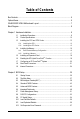
Table of Contents Box Contents ................................................................................................................. 6 Optional Items................................................................................................................. 6 GA-MA790GP-UD4H Motherboard Layout .................................................................... 7 Block Diagram................................................................................................................
2-13 2-14 Save & Exit Setup ......................................................................................... 58 Exit Without Saving ....................................................................................... 58 Chapter 3 Drivers Installation ...................................................................................... 59 3-1 Installing Chipset Drivers ............................................................................... 59 3-2 3-3 3-4 3-5 Application Software ...
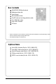
Box Contents GA-MA790GP-UD4H motherboard Motherboard driver disk User's Manual Quick Installation Guide One IDE cable and one floppy disk drive cable Four SATA 3Gb/s cables 2-port USB 2.0 bracket I/O Shield • The box contents above are for reference only and the actual items shall depend on product package you obtain. The box contents are subject to change without notice. • The motherboard image is for reference only. Optional Items 2-port USB 2.0 bracket (Part No.
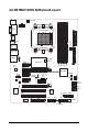
GA-MA790GP-UD4H Motherboard Layout CPU_FAN KB_MS DVI VGA ATX_12V_2X4 PWR_FAN 1394 SPDIF_IO CODEC PCIEX8_1 F_USB2 BATTERY CLR_CMOS F_USB1 PCIEX1_3 GA-MA790GP-UD4H IDE DDR2_4 AMD SB750 M_BIOS B_ BIOS SYS_FAN1 PCIEX1_2 DDR2_3 DDR2_1 PCIEX16_1 CD_IN IT8718 Memory AMD 790GX DDR2_2 RTL 8111C SidePort PCIEX1_1 F_USB4 F_USB3 AUDIO SATA2_4 SATA2_5 SATA2_2 SATA2_3 PCI1 TSB43AB23 PCI2 F_1394_1 F_1394_2 COM PWR_LED F_AUDIO LAN USB USB OPTICAL ATX HDMI Socket AM2+/AM2 CI FDD SYS_
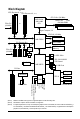
Block Diagram 2 PCI Express x8 PCIe CLK (100 MHz) (Note 3) 1 PCI Express x16 (Note 3) AMD Socket AM2+/AM2 CPU or CPU CLK+/-(200 MHz) DDR2 1200 (Note 1) /1066/ 800/ MHz DIMM Dual Channel Memory Hyper Transport 3.
Chapter 1 Hardware Installation 1-1 Installation Precautions The motherboard contains numerous delicate electronic circuits and components which can become damaged as a result of electrostatic discharge (ESD). Prior to installation, carefully read the user's manual and follow these procedures: • Prior to installation, do not remove or break motherboard S/N (Serial Number) sticker or warranty sticker provided by your dealer. These stickers are required for warranty validation.
1-2 Product Specifications CPU Hyper Transport Bus Chipset Memory Integrated Memory Audio LAN Expansion Slots Support for Socket AM2+/AM2 processors: AMD Phenom TM FX processor/AMD Phenom TM X4 processor/ AMD Phenom TM X3 processor/AMD Athlon TM X2 processor/ AMD Athlon TM processor/AMD Sempron TM X2 processor/ AMD Sempron TM processor (Go to GIGABYTE's website for the latest CPU support list.) 5200 MT/s North Bridge: AMD 790GX South Bridge: AMD SB750 4 x 1.
Internal Connectors Back Panel Connectors I/O Controller Hardware Monitor BIOS 1 x 24-pin ATX main power connector 1 x 8-pin ATX 12V power connector 1 x floppy disk drive connector 1 x IDE connector 6 x SATA 3Gb/s connectors 1 x CPU fan header 2 x system fan headers 1 x power fan header 1 x front panel header 1 x front panel audio header 1 x CD In connector 1 x S/PDIF In/Out header 2 x IEEE 1394a headers 4 x USB 2.0/1.
Unique Features Bundled Software Operating System Form Factor Support for @BIOS Support for Q-Flash Support for Virtual Dual BIOS Support for Download Center Support for Xpress Install Support for Xpress Recovery2 Support for EasyTune (Note 7) Support for Easy Energy Saver (Note 8) Norton Internet Security (OEM version) Support for Microsoft ® Windows ® Vista/XP ATX Form Factor; 30.5cm x 24.
1-3 Installing the CPU and CPU Cooler Read the following guidelines before you begin to install the CPU: • Make sure that the motherboard supports the CPU. (Go to GIGABYTE's website for the latest CPU support list.) • Always turn off the computer and unplug the power cord from the power outlet before installing the CPU to prevent hardware damage. • Locate the pin one of the CPU. The CPU cannot be inserted if oriented incorrectly. • Apply an even and thin layer of thermal grease on the surface of the CPU.
B. Follow the steps below to correctly install the CPU into the motherboard CPU socket. Before installing the CPU, make sure to turn off the computer and unplug the power cord from the power outlet to prevent damage to the CPU. CPU Socket Locking Lever Step 1: Completely lift up the CPU socket locking lever. Step 2: Align the CPU pin one (small triangle marking) with the triangle mark on the CPU socket and gently insert the CPU into the socket. Make sure that the CPU pins fit perfectly into their holes.
1-3-2 Installing the CPU Cooler Follow the steps below to correctly install the CPU cooler on the CPU. (The following procedure uses the GIGABYTE cooler as the example.) Step 1: Apply an even and thin layer of thermal grease on the surface of the installed CPU. Step 2: Place the CPU cooler on the CPU. Step 3: Hook the CPU cooler clip to the mounting lug on one side of the retention frame.
1-4 Installing the Memory Read the following guidelines before you begin to install the memory: • Make sure that the motherboard supports the memory. It is recommended that memory of the same capacity, brand, speed, and chips be used. (Go to GIGABYTE's website for the latest memory support list.) • Always turn off the computer and unplug the power cord from the power outlet before installing the memory to prevent hardware damage. • Memory modules have a foolproof design.
1-4-2 Installing a Memory Before installing a memory module , make sure to turn off the computer and unplug the power cord from the power outlet to prevent damage to the memory module. DDR2 DIMMs are not compatible to DDR DIMMs. Be sure to install DDR2 DIMMs on this motherboard. Notch DDR2 DIMM A DDR2 memory module has a notch, so it can only fit in one direction. Follow the steps below to correctly install your memory modules in the memory sockets. Step 1: Note the orientation of the memory module.
1-5 Installing an Expansion Card Read the following guidelines before you begin to install an expansion card: • Make sure the motherboard supports the expansion card. Carefully read the manual that came with your expansion card. • Always turn off the computer and unplug the power cord from the power outlet before installing an expansion card to prevent hardware damage.
1-6 Enabling the ATI Hybrid CrossFireXTM Function Combining the onboard GPU with a discrete graphics card, ATI Hybrid CrossFireX can provide significantly advanced display performance for AMD platform. This section give instructions on configuring an ATI Hybrid CrossFireX system. A. Before you begin-1. Supported Operating Systems: Windows Vista and Windows XP*. 2. BIOS Setup: Enter BIOS Setup to set the following items under the Advanced BIOS Features menu: • Set Internal Graphics Mode to UMA+SidePort.
1-7 Configuring an ATI CrossFireXTM System To enable CrossFireX TM technology, you need two graphics cards that support ATI CrossFire TM technology. Before You Begin-A. Power Requirements: Use a power supply that is able to provide sufficient power to fully support an CrossFireX configuration and other components in your system. We recommend a power supply that provides at least 20A 12V current. The exact power requirements depend on your overall system configurations. B.
1-8 Back Panel Connectors PS/2 Keyboard and PS/2 Mouse Port Use the upper port (green) to connect a PS/2 mouse and the lower port (purple) to connect a PS/2 keyboard. D-Sub Port The D-Sub port supports a 15-pin D-Sub connector. Connect a monitor that supports D-Sub connection to this port. DVI-D Port The DVI-D port supports DVI-D specifictation. Connect a monitor that supports DVI-D connection to this port.
A. Dual Display Configurations: This motherboard provides three ports for video output: DVI-D, HDMI and D-Sub. The table below shows the supported dual display configurations. Dual Combination Supported or Not DVI-D + D-Sub Yes Display DVI-D + HDMI No HDMI + D-Sub Yes B. Playback of HD DVD and Blu-ray Discs: In order to get better playback quality, when playing the HD DVD or Blu-ray discs, refer to the recommended system requirements (or better) below.
Center/Subwoofer Speaker Out Jack (Orange) Use this audio jack to connect center/subwoofer speakers in a 5.1/7.1-channel audio configuration. Rear Speaker Out Jack (Black) Use this audio jack to connect rear speakers in a 4/5.1/7.1-channel audio configuration. Side Speaker Out Jack (Gray) Use this audio jack to connect side speakers in a 7.1-channel audio configuration. Line In Jack (Blue) The default line in jack . Use this audio jack for line in devices such as an optical drive, walkman, etc.
1-9 Internal Connectors 1 3 2 6 7 13 11 14 4 16 15 20 9 18 1) 2) 3) 4) 5) 6) 7) 8) 9) 10) ATX_12V_2X4 ATX CPU_FAN SYS_FAN1 SYS_FAN2 PWR_FAN IDE FDD SATA2_0 / 1 / 2 / 3 / 4 / 5 PWR_LED 17 19 5 10 8 11) 12) 13) 14) 15) 16) 17) 18) 19) 20) 12 BATTERY F_PANEL F_AUDIO CD_IN SPDIF_IO F_USB1 / F_USB2 / F_USB3 / F_USB4 F_1394_1 / F_1394_2 COM CI CLR_CMOS Read the following guidelines before connecting external devices: • First make sure your devices are compliant with the connectors you wish to co
1/2) ATX_12V_2X4/ATX (2x4 12V Power Connector and 2x12 Main Power Connector) With the use of the power connector, the power supply can supply enough stable power to all the components on the motherboard. Before connecting the power connector, first make sure the power supply is turned off and all devices are properly installed. The power connector possesses a foolproof design. Connect the power supply cable to the power connector in the correct orientation.
3/4/5/6) CPU_FAN/SYS_FAN1/SYS_FAN2/PWR_FAN (Fan Headers) The motherboard has a 4-pin CPU fan header (CPU_FAN), a 3-pin (SYS_FAN2) and a 4-pin (SYS_FAN1) system fan headers, and a 3-pin power fan header (PWR_FAN). Most fan headers possess a foolproof insertion design. When connecting a fan cable, be sure to connect it in the correct orientation (the black connector wire is the ground wire). The motherboard supports CPU fan speed control, which requires the use of a CPU fan with fan speed control design.
8) FDD (Floppy Disk Drive Connector) This connector is used to connect a floppy disk drive. The types of floppy disk drives supported are: 360 KB, 720 KB, 1.2 MB, 1.44 MB, and 2.88 MB. Before connecting a floppy disk drive, be sure to locate pin 1 of the connector and the floppy disk drive cable. The pin 1 of the cable is typically designated by a stripe of different color.
10) PWR_LED (System Power LED Header) This header can be used to connect a system power LED on the chassis to indicate system power status. The LED is on when the system is operating. The LED keeps blinking when the system is in S1 sleep state. The LED is off when the system is in S3/S4 sleep state or powered off (S5). Pin No.
12) F_PANEL (Front Panel Header) Connect the power switch, reset switch, speaker and system status indicator on the chassis front panel to this header according to the pin assignments below. Note the positive and negative pins before connecting the cables.
13) F_AUDIO (Front Panel Audio Header) The front panel audio header supports Intel High Definition audio (HD) and AC'97 audio. You may connect your chassis front panel audio module to this header. Make sure the wire assignments of the module connector match the pin assignments of the motherboard header. Incorrect connection between the module connector and the motherboard header will make the device unable to work or even damage it. 10 9 2 1 For HD Front Panel Audio: Pin No.
15) SPDIF_IO (S/PDIF In/Out Header, Red) This header supports digital S/PDIF in/out. Via an optional S/PDIF in and out cable, this header can connect to an audio device that supports digital audio out and an audio system that supports digital audio in. For purchasing the optional S/PDIF in and out cable, please contact the local dealer. Pin No. 1 6 5 2 1 Definition Power 2 No Pin 3 SPDIF 4 5 SPDIFI GND 6 GND 16) F_USB1/F_USB2/F_USB3/F_USB4 (USB Headers, Yellow) The headers conform to USB 2.0/1.
17) F_1394_1/F_1394_2 (IEEE 1394a Header, Gray) The headers conform to IEEE 1394a specification. Each IEEE 1394a header can provide one IEEE 1394a port via an optional IEEE 1394a bracket. For purchasing the optional IEEE 1394a bracket, please contact the local dealer. Pin No. 9 1 10 2 Definition 1 2 TPA+ TPA- 3 GND 4 GND 5 6 TPB+ TPB- 7 Power (12V) 8 Power (12V) 9 10 No Pin GND • Do not plug the USB bracket cable into the IEEE 1394a header.
19) CI (Chassis Intrusion Header) This motherboard provides a chassis detection feature that detects if the chassis cover has been removed. This function requires a chassis with chassis intrusion detection design. Pin No. 1 Definition 1 Signal 2 GND 20) CLR_CMOS (Clearing CMOS Jumper) Use this jumper to clear the CMOS values (e.g. date information and BIOS configurations) and reset the CMOS values to factory defaults.
GA-MA790GP-UD4H Motherboard - 34 -
Chapter 2 BIOS Setup BIOS (Basic Input and Output System) records hardware parameters of the system in the CMOS on the motherboard. Its major functions include conducting the Power-On Self-T est (POST) during system startup, saving system parameters and loading operating system, etc. BIOS includes a BIOS Setup program that allows the user to modify basic system configuration settings or to activate certain system features.
2-1 Startup Screen The following screens may appear when the computer boots. A. The LOGO Screen (Default) Function Keys B. The POST Screen Award Modular BIOS v6.00PG, An Energy Star Ally Copyright (C) 1984-2008, Award Software, Inc. Motherboard Model BIOS Version GA-MA790GP-UD4H E6c . . . .
2-2 The Main Menu Once you enter the BIOS Setup program, the Main Menu (as shown below) appears on the screen. Use arrow keys to move among the items and press to accept or enter a sub-menu. (Sample BIOS Version: E6c) CMOS Setup Utility-Copyright (C) 1984-2008 Award Software MB Intelligent Tweaker(M.I.T.
The Functions of the and keys (For the Main Menu Only) F11 : Save CMOS to BIOS This function allows you to save the current BIOS settings to a profile. You can create up to 8 profiles (Profile 1-8) and name each profile. First enter the profile name (to erase the default profile name, use the SPACE key) and then press to complete.
2-3 MB Intelligent Tweaker(M.I.T.) CMOS Setup Utility-Copyright (C) 1984-2008 Award Software MB Intelligent Tweaker(M.I.T.) HT Link Frequency CPU Clock Ratio CPU North Bridge Freq.
HT Link Frequency Allows you to manually set the frequency for the HT Link between the CPU and chipset. Auto BIOS will automatically adjust the HT Link frequency. (Default) 200 MHz~1 GHz Sets HT Link Frequency to 200 MHz~1 GHz. CPU Clock Ratio Allows you to alter the clock ratio for the installed CPU. The adjustable range is dependent on the CPU being used. CPU North Bridge Freq. (Note) Allows you to alter the memory controller frequency for the installed CPU.
DRAM Configuration CMOS Setup Utility-Copyright (C) 1984-2008 Award Software DRAM Configuration x x x x x x x x x x x x x x DDRII Timing Items CAS# latency RAS to CAS R/W Delay Row Precharge Time Minimum RAS Active Time 1T/2T Command Timing TwTr Command Delay Trfc0 for DIMM1 Trfc2 for DIMM2 Trfc1 for DIMM3 Trfc3 for DIMM4 Write Recovery Time Precharge Time Row Cycle Time RAS to RAS Delay : Move Enter: Select F5: Previous Values [Auto] Auto Auto Auto Auto Auto Auto Auto Auto Auto Auto Auto Auto Auto A
Precharge Time Options are: Auto (default), 2T, 3T. Row Cycle Time Options are: Auto (default), 11T~26T. RAS to RAS Delay Options are: Auto (default), 2T~5T. ******** System Voltage Optimized ******** System Voltage Control Determines whether to manually set the system voltages. Auto lets BIOS automatically set the system voltages as required. Manual allows all voltage control items below to be configurable. (Default: Auto) SouthBridge Volt Control Allows you to set the South Bridge voltage.
2-4 Standard CMOS Features CMOS Setup Utility-Copyright (C) 1984-2008 Award Software Standard CMOS Features Date (mm:dd:yy) Time (hh:mm:ss) Tue, Nov 11 2008 18:25:04 IDE Channel 0 Master IDE Channel 0 Slave IDE Channel 1 Master IDE Channel 1 Slave IDE Channel 2 Master IDE Channel 2 Slave IDE Channel 3 Master IDE Channel 3 Slave [None] [None] [None] [None] [None] [None] [None] [None] Drive A Floppy 3 Mode Support [1.44M, 3.
Access Mode Sets the hard drive access mode. Options are: Auto (default), Large. The following fields display your hard drive specifications. If you wish to enter the parameters manually, refer to the information on the hard drive. Capacity Approximate capacity of the currently installed hard drive. Cylinder Number of cylinders. Head Number of heads. Precomp Write precompensation cylinder. Landing Zone Landing zone. Sector Number of sectors.
2-5 Advanced BIOS Features CMOS Setup Utility-Copyright (C) 1984-2008 Award Software Advanced BIOS Features Internal Graphics Mode UMA Frame Buffer Size x Surround View Onboard VGA output connect Virtualization Patch AMD TLB Erratum (Note) AMD K8 Cool&Quiet control Hard Disk Boot Priority First Boot Device Second Boot Device Third Boot Device Password Check HDD S.M.A.R.T.
Virtualization Virtualization allows a platform to run multiple operating systems and applications in independent partitions. With virtualization, one computer system can function as multiple virtual systems. (Default: Disabled) Patch AMD TLB Erratum (Note) Enables or disables the Patch AMD TLB Erratum function.
Init Display First Specifies the first initiation of the monitor display from the installed PCI graphics card, PCI Express graphics card, or the onboard VGA. PCI Slot Sets the PCI graphics card as the first display.(Default) OnChipVGA Sets the onboard VGA as the first display. PEG Sets the PCI Express graphics card on the PCIEX16_1 slot as the first display. PEG1 Sets the PCI Express graphics card on the PCIEX8_1 slot as the first display.
2-6 Integrated Peripherals CMOS Setup Utility-Copyright (C) 1984-2008 Award Software Integrated Peripherals OnChip IDE Channel OnChip SATA Controller OnChip SATA Type x OnChip SATA Port4/5 Type Onboard Audio Function Onboard 1394 Function Onboard LAN Function SMART LAN Onboard LAN Boot ROM OnChip USB Controller USB EHCI Controller USB Keyboard Support USB Mouse Support Legacy USB storage detect Onboard Serial Port 1 : Move Enter: Select F5: Previous Values [Enabled] [Enabled] [Native IDE] [IDE] [E
Onboard LAN Function Enables or disables the onboard LAN function. (Default: Enabled) If you wish to install a 3rd party add-in network card instead of using the onboard LAN, set this item to Disabled. SMART LAN (LAN Cable Diagnostic Function) CMOS Setup Utility-Copyright (C) 1984-2008 Award Software SMART LAN Start detecting at Port.....
Onboard LAN Boot ROM Allows you to decide whether to activate the boot ROM integrated with the onboard LAN chip. (Default: Disabled) OnChip USB Controller Enables or disables the integrated USB 1.1 controller. (Default: Enabled) USB EHCI Controller Enables or disables the integrated USB 2.0 controller. (Default: Enabled) USB Keyboard Support Allows USB keyboard to be used in MS-DOS. (Default: Disabled) USB Mouse Support Allows USB mouse to be used in MS-DOS.
2-7 Power Management Setup CMOS Setup Utility-Copyright (C) 1984-2008 Award Software Power Management Setup ACPI Suspend Type Soft-Off by Power button USB Wake Up from S3 Modem Ring Resume PME Event Wake Up HPET Support (Note) Power On By Mouse Power On By Keyboard x KB Power ON Password AC Back Function Power-On by Alarm x Date (of Month) x Resume Time (hh:mm:ss) : Move Enter: Select F5: Previous Values [S3(STR)] [Instant-off] [Enabled] [Disabled] [Enabled] [Enabled] [Disabled] [Disabled] Enter [So
PME Event Wake Up Allows the system to be awakened from an ACPI sleep state by a wake-up signal from a PCI or PCIe device. Note: To use this function, you need an ATX power supply providing at least 1A on the +5VSB lead. (Default: Enabled) HPET Support (Note) Enables or disables High Precision Event Timer (HPET) for Windows ® Vista ® operating system. (Default: Enabled) Power On By Mouse Allows the system to be turned on by a PS/2 mouse wake-up event.
2-8 PnP/PCI Configurations CMOS Setup Utility-Copyright (C) 1984-2008 Award Software PnP/PCI Configurations PCI1 IRQ Assignment PCI2 IRQ Assignment : Move Enter: Select F5: Previous Values [Auto] [Auto] +/-/PU/PD: Value F6: Fail-Safe Defaults Item Help Menu Level F10: Save ESC: Exit F1: General Help F7: Optimized Defaults PCI1 IRQ Assignment Auto 3,4,5,7,9,10,11,12,14,15 BIOS auto-assigns IRQ to the first PCI slot. (Default) Assigns IRQ 3,4,5,7,9,10,11,12,14,15 to the first PCI slot.
2-9 PC Health Status CMOS Setup Utility-Copyright (C) 1984-2008 Award Software PC Health Status Reset Case Open Status Case Opened Vcore DDR2 1.8V +3.3V +12V Current System Temperature Current CPU Temperature Current CPU FAN Speed Current SYSTEM FAN1 Speed Current SYSTEM FAN2 Speed Current POWER FAN Speed CPU Warning Temperature CPU FAN Fail Warning SYSTEM FAN1 Fail Warning SYSTEM FAN2 Fail Warning POWER FAN Fail Warning CPU Smart FAN Control : Move Enter: Select F5: Previous Values [Disabled] No 1.
Reset Case Open Status Keeps or clears the record of previous chassis intrusion status. Enabled clears the record of previous chassis intrusion status and the Case Opened field will show "No" at next boot. (Default: Disabled) Case Opened Displays the detection status of the chassis intrusion detection device attached to the motherboard CI header. If the system chassis cover is removed, this field will show "Y es", otherwise it will show "No".
2-10 Load Fail-Safe Defaults CMOS Setup Utility-Copyright (C) 1984-2008 Award Software MB Intelligent Tweaker(M.I.T.
2-12 Set Supervisor/User Password CMOS Setup Utility-Copyright (C) 1984-2008 Award Software MB Intelligent Tweaker(M.I.T.
2-13 Save & Exit Setup CMOS Setup Utility-Copyright (C) 1984-2008 Award Software MB Intelligent Tweaker(M.I.T.
Chapter 3 Drivers Installation • Before installing the drivers, first install the operating system. (The following instructions use Windows XP as the example operating system.) • After installing the operating system, insert the motherboard driver disk into your opti cal drive. The driver Autorun screen is automatically displayed which looks like that shown in the screen shot below.
3-2 Application Software This page displays all the utilities and applications that GIGABYTE develops and some free software. You can click the Install button on the right of an item to install it. 3-3 Technical Manuals This page provides GIGABYTE's application guides, content descriptions for this driver disk, and the motherboard manuals.
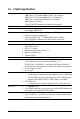
3-4 Contact For the detailed contact information of the GIGABYTE Taiwan headquarter or worldwide branch of fices, click the URL on this page to link to the GIGABYTE Website. 3-5 System This page provides the basic system information.
3-6 Download Center To update the BIOS, drivers, or applications, click the Download Center button to link to the GIGABYTE Web site. The latest version of the BIOS, drivers, or applications will be displayed.
Chapter 4 Unique Features 4-1 Xpress Recovery2 Xpress Recovery2 is a utility that allows you to quickly compress and back up your system data and perform restoration of it. Supporting NTFS, FAT32, and FAT16 file systems, Xpress Recovery2 can back up data on PATA and SATA hard drives and restore it. Before You Begin: • Xpress Recovery2 will check the first physical hard drive* for the operating system.
Installation and Configuration (The following procedure uses Windows XP as the example operating system.) A. Installing Windows XP and Partitioning the Hard Drive 1. 2. Set CD-ROM drive as the first boot device under "Advanced BIOS Features" in the BIOS Setup program. Save the changes and exit. When partitioning your hard drive (Figure 1), make sure to leave unallocated space for Xpress Recovery2 (10 GB or more is recommended; actual size requirements vary, depending on the amount of data) (Figure 2).
4. After the operating system is installed, right-click the My Computer icon on your desktop and select Manage (Figure 4). Go to Computer Management to check disk allocation. Xpress Recovery2 will save the backup file to the unallocated space (black stripe along the top)(Figure 5). Please note that if there is no enough unallocated space, Xpress Recovery2 cannot save the backup file. Figure 4 5.
B. Accessing Xpress Recovery2 1. Boot from the motherboard driver disk to access Xpress Recovery2 for the first time. When you see the following message: Press any key to startup Xpress Recovery2 (Figure 8), press any key to enter Xpress Recovery2. . . Boot from CD/DVD: Press any key to startup XpressRecovery2..... 2. Figure 8 After you use the backup function in Xpress Recovery2 for the first time, Xpress Recovery2 will stay permanent in your hard drive.
D. Using the Restore Function in Xpress Recovery2 Select RESTORE to restore the backup to your hard drive in case the system breaks down. The RESTORE option will not be present if no backup is created before (Figure 13, 14). Figure 13 Figure 14 E. Removing the Backup 1. 2. If you wish to remove the backup file, select REMOVE (Figure 15). After the backup file is removed, no backup image file will be present in Disk Management and hard drive space will be freed up (Figure 16). Figure 15 Figure 16 F.
4-2 BIOS Update Utilities GIGABYTE motherboards provide two unique BIOS update tools, Q-Flash TM and @BIOS TM. GIGABYTE Q-Flash and @BIOS are easy-to-use and allow you to update the BIOS without the need to enter MSDOS mode. Additionally, this motherboard features the DualBIOS TM design, which enhances protection for the safety and stability of your computer by adding one more physical BIOS chip. What is DualBIOSTM ? Motherboards that support DualBIOS have two BIOS onboard, a main BIOS and a backup BIOS.
B. Updating the BIOS When updating the BIOS, choose the location where the BIOS file is saved. The follow procedure assumes that you save the BIOS file to a floppy disk. Step 1: 1. Insert the floppy disk containing the BIOS file into the floppy disk drive. In the main menu of QFlash, use the up or down arrow key to select Update BIOS from Drive and press . • The Save Main BIOS to Drive option allows you to save the current BIOS file.
Step 4: Press and then to exit Q-Flash and reboot the system. As the system boots, you should see the new BIOS version is present on the POST screen. Step 5: During the POST, press to enter BIOS Setup. Select Load Optimized Defaults and press to load BIOS defaults. System will re-detect all peripherals devices after a BIOS update, so we recommend that you reload BIOS defaults. CMOS Setup Utility-Copyright (C) 1984-2008 Award Software MB Intelligent Tweaker(M.I.T.
4-2-2 Updating the BIOS with the @BIOS Utility A. Before You Begin: 1. 2. 3. 4. In Windows, close all applications and TSR (Terminate and Stay Resident) programs. This helps prevent unexpected failures when performing a BIOS update. During the BIOS update process, ensure the Internet connection is stable and do NOT interrupt the Internet connection (for example, avoid a power loss or switching off the Internet). Failure to do so may result in a corrupted BIOS or a system that is unable to start.
4-3 EasyTune 6 GIGABYTE's EasyTune 6 is a simple and easy-to-use interface that allows users to fine-tune their system settings or do overclock/overvoltage in Windows environment. The user-friendly EasyTune 6 interface also includes tabbed pages for CPU and memory information, lettings users read their systemrelated information without the need to install additional software. The EasyTune 6 Interface Tabs Information Tab Function The CPU tab provides information on the installed CPU and motherboard.
4-4 Easy Energy Saver GIGABYTE Easy Energy Saver (Note 1) is a revolutionary technology that delivers unparalleled power savings with a click of the button. Featuring an advanced proprietary software design, GIGABYTE Easy Energy Saver is able to provide exceptional power savings and enhanced power efficiency without sacrificing computing performance. The Easy Energy Saver Interface A. Meter Mode In Meter Mode, GIGABYTE Easy Energy Saver shows how much power they have saved in a set period of time.
B. Total Mode In Total Mode, users are able to see how much total power savings they have accumulated in a set period of time since activating Easy Energy Saver for the first time (Note 4) .
Chapter 5 Appendix 5-1 Configuring SATA Hard Drive(s) To configure SATA hard drive(s), follow the steps below: A. B. C. D. E. Install SATA hard drive(s) in your computer . Configure SATA controller mode in BIOS Setup. Configure a RAID array in RAID BIOS. (Note 1) Make a floppy disk containing the SA TA RAID/AHCI driver for Windows XP. (Note 2) Install the SATA RAID/AHCI driver and operating system.
B. Configuring SATA controller mode in BIOS Setup Make sure to configure the SA TA controller mode correctly in system BIOS Setup . Step 1: Turn on your computer and press to enter BIOS Setup during the POST (Power-On Self-Test). Ensure OnChip SATA Controller is enabled under Integrated Peripherals. To enable RAID for the SATA2_0/1/2/3 connectors, set OnChip SATA Type to RAID.
C. Configuring RAID set in RAID BIOS Enter the RAID BIOS setup utility to configure a RAID array. Skip this step if you do not want to create RAID. Step 1: After the POST memory test begins and before the operating system boot begins, look for a message which says "Press to enter FastBuild (tm) Utility" (Figure 2). Hit the + key to enter the RAID BIOS setup utility. RAID Option ROM Version 3.0.1540.33 (c) 2008 Advanced Micro Devices, Inc. All rights reserved. No Array is defined..
Create Arrays Manually To create a new array, press <2> to enter the Define LD window (Figure 4). The Define LD selection from the Main Menu allows users to begin the process of manually defining the drive elements and RAID levels for one or multiple disk arrays attached to the AMD SB750 controller. FastBuild (tm) Utility (c) 2008 Advanced Micro Devices, Inc.
In the following procedure, we'll create RAID 0 as an example. 1. Under the RAID Mode section, press the key to select RAID 0. 2. Set the Stripe Block size. 64 KB is the default. 3. Under the Drives Assignments section, press the up or down arrow key to highlight a drive. 4. Press the key or to change the Assignment option to Y. This action adds the drive to the disk array . The Total Drv section will show the number of disks assigned. 5. Press + keys to save the information.
Delete an Array The Delete Array menu option allows for deletion of disk array assignments. Deleting an existing disk array could result in loss of data. Record all array information including the array type, the disk members, and stripe block size in case you wish to undo a deletion. 1. 2. 3. To delete an array, press <3> in the Main Menu to enter the Delete LD Menu. Then highlight the array you wish to delete and press the key or the + keys.
5-1-2 Making a SATA RAID/AHCI Driver Diskette for Windows XP (Required for AHCI and RAID Mode) To successfully install operating system onto SA TA hard drive(s) that is/are configured to RAID/AHCI mode, you need to install the SA TA controller driver during the OS installation. Without the driver , the hard drive may not be recognized during the Windows setup process. First of all, copy the driver for the SATA controller from the motherboard driver disk to a floppy disk.
5-1-3 Installing the SATA RAID/AHCI Driver and Operating System You are ready to install W indows Vista/XP onto your hard drive(s). The following is an example of Windows XP and Vista installation. A. Installing Windows XP Step 1: Restart your system to boot from the Windows XP setup disk and press as soon as you see the message "Press F6 if you need to install a 3rd party SCSI or RAID driver" (Figure 1).
Step 3: When Setup correctly recognizes the AMD SB750 SATA RAID/AHCI driver in the floppy disk, a controller menu similar to Figure 3 below will appear. Use the arrow keys to select AMD AHCI Compatible RAID Controller-x86 platform and press . Windows Setup You have chosen to configure a SCSI Adapter for use with Windows, using a device support disk provided by an adapter manufacturer. Select the SCSI Adapter you want from the following list, or press ESC to return to the previous screen.
Step 4: After the SATA RAID/AHCI driver installation is completed, you can proceed with the W indows XP installation. WindowsXP Professional Setup Welcome to Setup. This port of the Setup program prepares Microsoft(R) Windows (R) XP to run on your computer. To set up Windows XP now, press ENTER. To repair a Windows XP installation using Recovery Console, press R. To quit Setup without installing Windows XP, press F3.
B. Installing Windows Vista (The procedure below assumes that only one RAID array exists in your system.) Step 1: Restart your system to boot from the Windows Vista setup disk and perform standard OS installation steps. When a screen similar to that below appears (RAID hard drive will not be detected at this stage), select Load Driver. (Figure 6). Figure 6 Step 2: Specify the location where the driver is saved (Figure 7).
Step 3: When a screen as shown in Figure 8 appears, select AMD AHCI Compatible RAID Controller and press Next. Figure 8 Step 4: After the driver is loaded, the RAID drive will appear. Select the RAID drive and then press Next to continue the OS installation (Figure 9).
Rebuilding an Array: Rebuilding is the process of restoring data to a hard drive from other drives in the array. Rebuilding applies only to fault-tolerant arrays such as RAID 1, RAID 5, or RAID 10 arrays. To replace the old drive, make sure to use a new drive of equal or greater capacity. The procedures below assume a new drive is added to replace a failed drive to rebuild a RAID 1 array.
5-2 Configuring Audio Input and Output 5-2-1 Configuring 2/4/5.1/7.1-Channel Audio The motherboard provides six audio jacks on the back panel which support 2/4/5.1/7.1-channel audio. The picture to the right shows the default audio jack Center/Subwoofer Line In Speaker Out assignments. Front Speaker Out Rear Speaker Out The integrated HD (High Definition) audio provides Mic In jack retasking capability that allows the user to change Side Speaker Out the function for each jack through the audio driver.
Step 2: Click the Audio I/O tab. In the speaker list on the left, select 2CH Speaker, 4CH Speaker, 6CH Speaker, or 8CH Speaker according to the type of speaker configuration you wish to set up. Step 3: Everytime you connect an audio device to an audio jack, the Connected device box appears. Select the device according to the type of device you connect. Then click OK to complete the configuration. B. Configuring Sound Effect: You may configure an audio environment on the Sound Effect tab. C.
5-2-2 Installing the S/PDIF In and Out Cable (Optional) The S/PDIF in and out cable provides S/PDIF in and S/PDIF out functionalities. Optical S/PDIF Out Coaxial S/PDIFOut Optical S/PDIF In Coaxial S/PDIFIn S/PDIF in: The S/PDIF in jacks allow you to input digital audio signals to the computer for audio processing. S/PDIF out: The S/PDIF out jacks can transmit audio signals to an external decoder for decoding to get the best audio quality.
Step 3: Connect a S/PDIF coaxial cable or a S/PDIF optical cable (either one) to an external decoder for transmitting the S/PDIF digital audio signals. S/PDIF Coaxial Cable S/PDIF Optical Cable B. Configuring S/PDIF out: Click the tool icon in the DIGITAL section. In the S/PDIF In/Out Settings dialog box, select an output sampling rate and select (or disable) the output source. Click OK to complete the configuration.
5-2-3 Enabling the Dolby Home Theater Function Before Dolby Home Theater is enabled, you get only 2-channel playback output (from the front speakers) when playing 2-channel stereo sources . You must play 4-, 5.1-, or 7.1channel content to get 4-, 5.1-, or 7.1- channel audio effects. With Dolby Home Theater enabled, 2-channel stereo content will be transformed into multi-channel audio, creating a virtual surround sound environment (Note). A.
5-2-4 Configuring Microphone Recording Step 1: After installing the audio driver, the Audio Manager will appear in your system tray. Doubleicon click the icon to access the Audio Control Panel. Step 2: Connect your microphone to the Mic in jack (pink) on the back panel or the Mic in jack (pink) on the front panel. Then configure the jack for microphone functionality. Note: The microphone functions on the front panel and back panel cannot be used at the same time.
Step 4: To hear the sound being recorded during the recording process when using the microphone function on the front panel, do not select the Mute check box under Front Pink In or Front Green In in Master Volume. It is recommended that you set the volume at a middle level. or To hear the sound being recorded during the recording process when using the microphone function on the back panel, do not select the Mute check box under Rear Pink In in Master Volume.
Step 6: To raise the recording and playing sound for the microphone, go to Options in Master Volume and select Advanced Controls. Click the Advanced button under a volume control option (e.g. Front Green In, Front Pink In). In the Other Controls field, select the 1 Microphone Boost check box. Step 7: After completion, click Start, point to All Programs, point to Accessories, point to Entertainment, and then click Sound Recorder to begin the sound recording.
5-3 Troubleshooting 5-3-1 Frequently Asked Questions To read more F AQs for your motherboard, please go to the Support\Motherboard\F AQ page on GIGABYTE's website. Q: In the BIOS Setup program, why are some BIOS options missing? A: Some advanced options are hidden in the BIOS Setup program. Press to enter BIOS Setup during the POST. In the Main Menu, press + to show the advanced options.
5-3-2 Troubleshooting Procedure If you encounter any troubles during system startup, follow the troubleshooting procedure below to solve the problem. START Turn off the power. Remove all peripherals, connecting cables, and power cord etc. Make sure the motherboard does not short-circuit with the chassis or other metal objects. No Yes Isolate the short circuit. The problem is verified and solved. Check if the CPU cooler is attached to the CPU securely.
A When the computer is turned on, is the CPU cooler running? Yes No The power supply, CPU or CPU socket might fail. The problem is verified and solved. Check if there is display on your monitor. Yes No The graphics card, expansion slot, or monitor might fail. The problem is verified and solved. Turn off the computer. Plugg in the keyboard and mouse and restart the computer. Check if the keyboard is working properly. No The keyboard or mouse might fail. Yes Press to enter BIOS Setup.
5-4 Regulatory Statements Regulatory Notices This document must not be copied without our written permission, and the contents there of must not be imparted to a third party nor be used for any unauthorized purpose. Contravention will be prosecuted. We believe that the information contained herein was accurate in all respects at the time of printing. GIGABYTE cannot, however, assume any responsibility for errors or omissions in this text.
Finally, we suggest that you practice other environmentally friendly actions by understanding and using the energy-saving features of this product (where applicable), recycling the inner and outer packaging (including shipping containers) this product was delivered in, and by disposing of or recycling used batteries properly.
- 101 - Appendix
GA-MA790GP-UD4H Motherboard - 102 -
Contact Us GIGA-BYTE TECHNOLOGY CO., LTD. Address: No.6, Bau Chiang Road, Hsin-Tien, NINGBO G.B.T. TECH. TRADING CO., LTD. (China) WEB address : http://www.gigabyte.cn Taipei 231, Taiwan TEL: +886-2-8912-4000 Shanghai TEL: +86-21-63410999 FAX: +886-2-8912-4003 FAX: +86-21-63410100 Tech. and Non-Tech. Support (Sales/Marketing) : Beijing http://ggts.gigabyte.com.tw WEB address (English): http://www.gigabyte.com.tw TEL: +86-10-62102838 FAX: +86-10-62102848 WEB address (Chinese): http://www.
G.B.T. TECHNOLOGY TRADING GMBH (Germany) WEB address : http://www.gigabyte.de G.B.T. TECH. CO., LTD. (U.K.) WEB address : http://www.giga-byte.co.uk GIGA-BYTE TECHNOLOGY B.V. (The Netherlands) WEB address : http://www.giga-byte.nl WEB address : http://www.gigabyte.se (Sweden) GIGABYTE TECHNOLOGY FRANCE (France) WEB address : http://www.gigabyte.fr WEB address : http://www.giga-byte.it (Italy) GIGA-BYTE SPAIN (Spain) WEB address : http://www.giga-byte.