GA-VM800PMC Intel® CoreTM 2 Duo / Intel® Pentium® D / Pentium® 4 / Celeron® D LGA775 Processor Motherboard User's Manual Rev. 1003 12ME-VM800PMC-1003R * The WEEE marking on the product indicates this product must not be disposed of with user's other household waste and must be handed over to a designated collection point for the recycling of waste electrical and electronic equipment!! * The WEEE marking applies only in European Union's member states.
Motherboard GA-VM800PMC Dec. 5, 2006 Motherboard GA-VM800PMC Dec.
Copyright © 2006 GIGA-BYTE TECHNOLOGY CO., LTD. All rights reserved. The trademarks mentioned in the manual are legally registered to their respective companies. Notice The written content provided with this product is the property of Gigabyte. No part of this manual may be reproduced, copied, translated, or transmitted in any form or by any means without Gigabyte's prior written permission. Specifications and features are subject to change without prior notice.
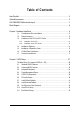
Table of Contents Item Checklist ................................................................................................................. 6 Optional Accessories ...................................................................................................... 6 GA-VM800PMC Motherboard Layout ............................................................................ 7 Block Diagram ................................................................................................................
Chapter 3 Drivers Installation ...................................................................................... 45 3-1 Install Chipset Drivers .................................................................................... 45 3-2 3-3 Software Application ....................................................................................... 46 Software Information ....................................................................................... 46 3-4 3-5 Hardware Information .........
Item Checklist IDE Cable x 1, FDD Cable x 1 SATA Cable x 1 I/O Shield * The items listed above are for reference only, and are subject to change without notice. Optional Accessories 2 Ports USB 2.0 Cable (Part Number: 12CR1-1UB030-51/R) 4 Ports USB 2.
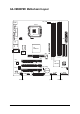
GA-VM800PMC Motherboard Layout CPU_FAN KB_MS VGA LPT COMA LGA775 ATX AGP PCI1 VIA VT6103L PCI3 SATA1 SATA0 CLR_CMOS SYS _FAN BATTERY CODEC SUR_CEN IDE1 IDE2 VIA VT8237R+ PCI2 CD_IN DDR1 BIOS DDRII1 F_AUDIO DDR2 AUDIO DDRII2 VIA P4M800 Pro GA-VM800PMC Winbond W83627 LAN USB USB ATX_12V CI F_USB2 COMB FDD F_USB1 SPDIF_IO -7- F_PANEL PWR_LED
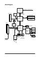
Block Diagram LGA 775 Processor AGP 4X/8X CPUCLK+/- (200/133 MHz) System Bus 800/533 MHz VGA Port 400/333 MHz DDR VIA P4M800 Pro DDRII 533/400 MHz RJ45 3 PCI VIA 6103L 2 Serial ATA VIA VT8237R+ BIOS LPC BUS Floppy AC97 Link Winbond W83627 LPT Port PS/2 KB/Mouse 8 USB Ports ATA 33/66/ 100/133 IDE Channels LINE-OUT PCI CLK (33 MHz) MIC LINE-IN 6 Channel CODEC -8- COMA/COMB
1-1 English Chapter 1 Hardware Installation Considerations Prior to Installation Preparing Your Computer The motherboard contains numerous delicate electronic circuits and components which can become damaged as a result of electrostatic discharge (ESD). Thus, prior to installation, please follow the instructions below: 1. Please turn off the computer and unplug its power cord. 2. When handling the motherboard, avoid touching any metal leads or connectors. 3.
English 1-2 Feature Summary CPU Storage O.
Rear Panel I/O I/O Control Hardware Monitor BIOS Additional Features Bundle Software Form Factor 2 USB 2.0/1.1 connectors for additional 4 USB 2.0/1.1 ports by cables 1 Chassis Intrusion connector 1 power LED connector 1 PS/2 keyboard port 1 PS/2 mouse port 1 parallel port 1 serial port 1 VGA port 4 USB 2.0/1.
English 1-3 Installation of the CPU and CPU Cooler Before installing the CPU, please comply with the following conditions: 1. Please make sure that the motherboard supports the CPU. 2. Please take note of the one indented corner of the CPU. If you install the CPU in the wrong direction, the CPU will not insert properly. If this occurs, please change the insert direction of the CPU. 3. Please add an even layer of heat sink paste between the CPU and heatsink. 4.
Male Push Pin The top of Female Push Pin Female Push Pin Fig.1 Please apply an even layer of CPU cooler paste on the surface of the installed CPU. Fig. 2 (Turning the push pin along the direction of arrow is to remove the CPU cooler, on the contrary, is to install.) Please note the direction of arrow sign on the male push pin doesn't face inwards before installation. (This instruction is only for Intel boxed fan) Fig.
Installation of Memory Before installing the memory modules, please comply with the following conditions: 1. Please make sure that the memory used is supported by the motherboard. It is recommended that memory of similar capacity, specifications and brand be used. 2. Before installing or removing memory modules, please make sure that the computer power is switched off to prevent hardware damage. 3. Memory modules have a foolproof insertion design. A memory module can be installed in only one direction.
Installation of Expansion Cards You can install your expansion card by following the steps outlined below: 1. Read the related expansion card's instruction document before installing the expansion card into the computer. 2. Remove your computer's chassis cover, screws and slot bracket from the computer. 3. Press the expansion card firmly into expansion slot in motherboard. 4. Be sure the metal contacts on the card are indeed seated in the slot. 5.
English 1-6 I/O Back Panel Introduction PS/2 Keyboard and PS/2 Mouse Connector To install a PS/2 port keyboard and mouse, plug the mouse to the upper port (green) and the keyboard to the lower port (purple). Parallel Port The parallel port allows connection of a printer, scanner and other peripheral devices. Serial Port Devices like mouses, modems, and etc. can be connected to Serial port. VGA Port Monitor can be connected to VGA port.
Connectors Introduction English 1-7 3 2 1 6 10 7 11 4 13 8 12 1) 2) 3) 4) 5) 6) 7) 8) 9) ATX_12V ATX (Power Connector) CPU_FAN SYS_FAN FDD IDE1 / IDE2 SATA0 / SATA1 F_PANEL PWR_LED 15 16 5 17 10) 11) 12) 13) 14) 15) 16) 17) 18) - 17 - 18 14 9 F_AUDIO CD_IN SPDIF_IO SUR_CEN F_USB1 / F_USB2 COMB CI CLR_CMOS BATTERY Hardware Installation
English 1/2) ATX_12V / ATX (Power Connector) With the use of the power connector, the power supply can supply enough stable power to all the components on the motherboard. Before connecting the power connector, please make sure that all components and devices are properly installed. Align the power connector with its proper location on the motherboard and connect tightly. The ATX_12V power connector mainly supplies power to the CPU.
The cooler fan power connector supplies a +12V power voltage via a 3-pin/4-pin(CPU_FAN) power connector and possesses a foolproof connection design. Most coolers are designed with color-coded power connector wires. A red power connector wire indicates a positive connection and requires a +12V power voltage. The black connector wire is the ground wire (GND). Remember to connect the CPU/system fan cable to the CPU_FAN/SYS_FAN connector to prevent CPU damage or system hanging caused by overheating.
English 6) IDE1 / IDE2 (IDE Connector) An IDE device connects to the computer via an IDE connector. One IDE connector can connect to one IDE cable, and the single IDE cable can then connect to two IDE devices (hard drive or optical drive). If you wish to connect two IDE devices, please set the jumper on one IDE device as Master and the other as Slave (for information on settings, please refer to the instructions located on the IDE device).
F_PANEL (Front Panel Connector) Please connect the power LED, PC speaker, reset switch and power switch etc. of your chassis front panel to the F_PANEL connector according to the pin assignments below.
English 9) PWR_LED The PWR_LED connector is connected with the system power indicator to indicate whether the system is on/off. It will blink when the system enters suspend mode(S1). Pin No. 1 2 3 1 Definition MPD+ MPDMPD- 10) F_AUDIO (Front Audio Panel Connector) Please make sure the pin assignment on the cable is the same as the pin assigment on the MB header. To find out if the chassis you are buying support front audio panel connector, please contact your dealer.
English 11) CD_IN (CD IN Connector) Connect CD-ROM or DVD-ROM audio out to the connector. 1 Pin No. 1 Definition CD-L 2 3 GND GND 4 CD-R 12) SPDIF_IO (S/PDIF In/Out Connector) The S/PDIF output is capable of providing digital audio to external speakers or compressed AC3 data to an external Dolby Digital Decoder. Use this feature only when your stereo system has digital input function. Use S/PDIF IN feature only when your device has digital output function.
English 13) SUR_CEN (Surround Center Connector) Please contact your nearest dealer for optional 6-Channel Audio Combo Kit. Pin No. 6 5 2 1 Definition 1 2 SUR OUTL SUR OUTR 3 4 GND No Pin 5 6 CENTER_OUT BASS_OUT 14) F_USB1 / F_USB2 (Front USB Connectors) Be careful with the polarity of the front USB connector. Check the pin assignment carefully while you connect the front USB cable, incorrect connection between the cable and connector will make the device unable to work or even damage it.
Be careful with the polarity of the COMB connector. Check the pin assignments while you connect the COMB cable. Please contact your nearest dealer for optional COMB cable. 9 1 10 2 Pin No. 1 Definition NDCDB- 2 3 NSINB NSOUTB 4 5 NDTRBGND 6 7 NDSRBNRTSB- 8 9 NCTSBNRIB- 10 No Pin 16) CI (Chassis Intrusion, Case Open) This 2-pin connector allows your system to detect if the chassis cover is removed. You can check the "Case Opened" status in BIOS Setup. Pin No.
English 17) CLR_CMOS (Clear CMOS) You may clear the CMOS data to its default values by this header. To clear CMOS, temporarily short the two pins. Default doesn't include the jumper to avoid improper use of this header. Open: Normal Short: Clear CMOS 18) BATTERY Danger of explosion if battery is incorrectly replaced. Replace only with the same or equivalent type recommended by the manufacturer. Dispose of used batteries according to the manufacturer's instructions. If you want to erase CMOS... 1.
BIOS (Basic Input and Output System) includes a CMOS SETUP utility which allows user to configure required settings or to activate certain system features. The CMOS SETUP saves the configuration in the CMOS SRAM of the motherboard. When the power is turned off, the battery on the motherboard supplies the necessary power to the CMOS SRAM. When the power is turned on, pushing the button during the BIOS POST (Power-On Self Test) will take you to the CMOS SETUP screen.
English : Boot Menu Select boot sequence for onboard (or add-on cards) device. Award Modular BIOS v6.00PG, An Energy Star Ally Copyright (C) 1984-2006, Award Software, Inc. VM800PMC D5 . . . . :BIOS Setup/Q-Flash, : Xpress Recovery2, : Boot Menu 10/31/2006-P4M800Pro-823-6A7L6G0FC-00 : Boot Menu Use < > or < > to select a device, then press enter to accept . Press to exit this menu.
English Standard CMOS Features This setup page includes all the items in standard compatible BIOS. Advanced BIOS Features This setup page includes all the items of Award special enhanced features. Integrated Peripherals This setup page includes all onboard peripherals. Power Management Setup This setup page includes all the items of Green function features. PnP/PCI Configuration This setup page includes all the configurations of PCI & PnP ISA resources.
English 2-1 Standard CMOS Features CMOS Setup Utility-Copyright (C) 1984-2006 Award Software Standard CMOS Features ` ` ` ` ` ` Date (mm:dd:yy) Time (hh:mm:ss) Wed, Nov 22 2006 10:40:9 IDE Channel 0 Master IDE Channel 0 Slave IDE Channel 1 Master IDE Channel 1 Slave IDE Channel 2 Master IDE Channel 3 Master [None] [None] [None] [None] [None] [None] Drive A Floppy 3 Mode Support [1.44M, 3.
Drive A The category identifies the types of floppy disk drive A that has been installed in the computer. None No floppy drive installed 360K, 5.25" 5.25 inch PC-type standard drive; 360K byte capacity. 1.2M, 5.25" 5.25 inch AT-type high-density drive; 1.2M byte capacity (3.5 inch when 3 Mode is Enabled). 720K, 3.5" 3.5 inch double-sided drive; 720K byte capacity 1.44M, 3.5" 3.5 inch double-sided drive; 1.44M byte capacity. (Default value) 2.88M, 3.5" 3.5 inch double-sided drive; 2.88M byte capacity.
English 2-2 Advanced BIOS Features CMOS Setup Utility-Copyright (C) 1984-2006 Award Software Advanced BIOS Features Init Display First VGA Share Memory Size ` Hard Disk Boot Priority First Boot Device Second Boot Device Third Boot Device Password Check CPU Hyper-Threading (Note) Limit CPUID Max.
Floppy LS120 Hard Disk CDROM ZIP USB-FDD USB-ZIP USB-CDROM USB-HDD Legacy LAN Disabled English First / Second / Third Boot Device Select your boot device priority by Floppy. Select your boot device priority by LS120. Select your boot device priority by Hard Disk. Select your boot device priority by CDROM. Select your boot device priority by ZIP. Select your boot device priority by USB-FDD. Select your boot device priority by USB-ZIP. Select your boot device priority by USB-CDROM.
English 2-3 Integrated Peripherals CMOS Setup Utility-Copyright (C) 1984-2006 Award Software Integrated Peripherals OnChip IDE Channel 0 OnChip IDE Channel 1 VIA Onboard LAN OnBoard LAN Boot ROM OnChip Serial ATA SATA Mode AC97 Audio USB 1.1 Controller USB 2.
Disabled Enabled English USB 2.0 Controller Disable USB 2.0 controller. Enable USB 2.0 controller. (Default value) USB Keyboard Support Enabled Disabled Enable USB keyboard support. Disable USB keyboard support. (Default value) USB Mouse Support Enabled Disabled Enable USB mouse support. Disable USB mouse support. (Default value) Legacy USB storage detect This option allows users to decide whether to detect USB storage devices, including USB flash drives and USB hard drives during POST.
English 2-4 Power Management Setup CMOS Setup Utility-Copyright (C) 1984-2006 Award Software Power Management Setup ACPI Suspend Type x USB Device Wake-Up From S3 Soft-Off by PWRBTN AC BACK Function Keyboard Power On Mouse Power On PME Event Wake Up Modem Ring Resume Resume by Alarm x Date (of Month) Alarm x Time (hh:mm:ss) Alarm KLJI: Move Enter: Select F5: Previous Values [S1(POS)] Disabled [Instant-Off] [Soft-Off] [Disabled] [Disabled] [Enabled] [Enabled] [Disabled] Everyday 0:0:0 +/-/PU/PD: Value
Disabled Enabled English Mouse Power On Disable this function. (Default value) Double click on PS/2 mouse left button to power on the system. PME Event Wake Up This feature requires an ATX power supply that provides at least 1A on the 5VSB lead. Disabled Disable this function. Enabled Enable PME as wake up event. (Default value) Modem Ring Resume An incoming call via modem can awake the system from any suspend state. Disabled Disable Modem Ring Resume function. Enabled Enable Modem Ring Resume function.
English 2-5 PnP/PCI Configurations CMOS Setup Utility-Copyright (C) 1984-2006 Award Software PnP/PCI Configurations PCI 1 IRQ Assignment PCI 2 IRQ Assignment PCI 3 IRQ Assignment KLJI: Move Enter: Select F5: Previous Values [Auto] [Auto] [Auto] +/-/PU/PD: Value F6: Fail-Safe Defaults Item Help Menu Level` F10: Save ESC: Exit F7: Optimized Defaults PCI 1 IRQ Assignment Auto 3,4,5,7,9,10,11,12,14,15 Auto assign IRQ to PCI 1. (Default value) Set IRQ 3,4,5,7,9,10,11,12,14,15 to PCI 1.
PC Health Status CMOS Setup Utility-Copyright (C) 1984-2006 Award Software PC Health Status Reset Case Open Status Case Opened VCORE DDR POWER +3.3V +12V System Temperature CPU Temperature Current SYS FAN Speed Current CPU FAN Speed System Warning Temp. CPU Warning Temp.
English CPU Warning Temperature 60 oC / 140 o F 70 oC / 158 o F 80 oC / 176 o F 90 oC / 194 o F Disabled Monitor CPU temperature at 60 oC / 140oF. Monitor CPU temperature at 70 oC / 158oF. Monitor CPU temperature at 80 oC / 176oF. Monitor CPU temperature at 90 oC / 194oF. Disable this function. (Default value) SYS / CPU FAN Fail Warning Disabled Enabled Disable fan fail warning function. (Default value) Enable fan fail warning function.
Load Fail-Safe Defaults English 2-7 CMOS Setup Utility-Copyright (C) 1984-2006 Award Software ` ` ` ` ` ` Standard CMOS Features Advanced BIOS Features Integrated Peripherals Power Management Setup PnP/PCI Configurations PC Health Status Load Fail-Safe Defaults Load Optimized Defaults Set Supervisor Password Set User Password Load Fail-Safe DefaultsSave (Y/N)? N Setup & Exit Exit Without Saving KLJI: Select Item F10: Save & Exit Setup ESC: Quit F8: Q-Flash Load Fail-Safe Defaults Fail-Safe defaults
English 2-9 Set Supervisor/User Password CMOS Setup Utility-Copyright (C) 1984-2006 Award Software ` ` ` ` ` ` Standard CMOS Features Advanced BIOS Features Integrated Peripherals Power Management Setup PnP/PCI Configurations Enter Password: PC Health Status Load Fail-Safe Defaults Load Optimized Defaults Set Supervisor Password Set User Password Save & Exit Setup Exit Without Saving KLJI: Select Item F10: Save & Exit Setup ESC: Quit F8: Q-Flash Change/Set/Disable Password When you select this functi
English 2-10 Save & Exit Setup CMOS Setup Utility-Copyright (C) 1984-2006 Award Software ` ` ` ` ` ` Standard CMOS Features Advanced BIOS Features Integrated Peripherals Power Management Setup PnP/PCI Configurations PC Health Status Load Fail-Safe Defaults Load Optimized Defaults Set Supervisor Password Set User Password Save & Exit Setup Save to CMOS and EXITExit (Y/N)? Y Saving Without KLJI: Select Item F10: Save & Exit Setup ESC: Quit F8: Q-Flash Save Data to CMOS Type "Y" will quit the Setup Utili
English GA-VM800PMC Motherboard - 44 -
Pictures below are shown in Windows XP. Insert the driver CD-title that came with your motherboard into your CD-ROM drive, the driver CD-title will auto start and show the installation guide. If not, please double click the CD-ROM device icon in "My computer", and execute the Setup.exe. 3-1 Install Chipset Drivers After insert the driver CD, "Xpress Install" will scan automatically the system and then list all the drivers that recommended to install.
English 3-2 Software Application This page displays all the tools that Gigabyte developed and some free software. You can click an item to install it. 3-3 Software Information This page lists the contents of software and drivers in this CD-title.
Hardware Information English 3-4 This page lists all device you have for this motherboard. 3-5 Contact Us Please see the last page for details.
English GA-VM800PMC Motherboard - 48 -
4-1 English Chapter 4 Appendix Unique Software Utilities (Not all model support these Unique Software Utilities, please check your MB features.) 4-1-1 EasyTune 5 Introduction EasyTune 5 presents the most convenient Windows based system performance enhancement and manageability utility. Featuring several powerful yet easy to use tools such as 1) Overclocking for enhancing system performance, 2) C.I.A. and M.I.B.
English 4-1-2 Xpress Recovery2 Introduction Xpress Recovery2 is designed to provide quick backup and restoration of hard disk data. Supporting Microsoft operating systems including Windows XP/2000/NT/98/Me and DOS, and file systems including FAT16, FAT32, and NTFS, Xpress Recovery2 is able to back up data on hard disks on PATA and SATA IDE controllers. After Xpress Recovery2 is executed from CD-ROM for the first time, it will stay permanent in your hard disk.
1. RESTORE: Restore the backed-up data to your hard disk. (This button will not appear if there is no backup file.) 2. BACKUP: Back up data from hard disk. 3. REMOVE: Remove previously-created backup files to release disk space. (This button will not appear if there is no backup file.) 4. REBOOT: Exit the main screen and restart the system. Limitations: 1. 2. 3. Not compatible to Xpress Recovery. For the use of Xpress Recovery2, a primary partition must be reserved.
English 4-1-3 Flash BIOS Method Introduction Method 1 : Q-FlashTM Utility Q-FlashTM is a BIOS flash utility embedded in Flash ROM. With this utility, users only have to stay in the BIOS menu when they want to update BIOS. Q-Flash TM allows users to flash BIOS without any utility in TM DOS or Windows. Using Q-Flash indicating no more fooling around with any complicated instructions and operating system since it is in the BIOS menu.
English Entering the Q-FlashTM utility: Step1: To use Q-Flash utility, you must press Del in the boot screen to enter BIOS menu. CMOS Setup Utility-Copyright (C) 1984-2004 Award Software Standard CMOS Features Advanced BIOS Features Integrated Peripherals Power Management Setup PnP/PCI Configurations PC Health Status MB Intelligent Tweaker(M.I.T.
English Using the Q-FlashTM utility: This section tells you how to update BIOS using the Q-Flash utility. As described in the "Before you begin" section above, you must prepare a floppy disk having the BIOS file for your motherboard and insert it to your computer. If you have already put the floppy disk into your system and have entered the Q-Flash utility, please follow the steps below to flash BIOS. Steps: 1.
English 3. Press Y button on your keyboard after you are sure to update BIOS. Then it will begin to update BIOS. The progress of updating BIOS will be displayed. Please do not take out the floppy disk when it begins flashing BIOS. 4. Press any keys to return to the Q-Flash menu when the BIOS updating procedure is completed. Dual BIOS Utility Boot From......................................... Main Bios Main ROM Type/Size.............................SST 49LF003A Backup ROM Type/Size.........................
English 6. Press Del to enter BIOS menu after system reboots. When you are in BIOS menu, move to Load Optimized Defaults item and press Enter to load BIOS Optimized Defaults. Normally the system redetects all devices after BIOS has been upgraded. Therefore, we highly recommend reloading the BIOS defaults after BIOS has been upgraded.
The Q-FlashBIOS utility screen consists of the following key components. Q-FlashTM utility bar Q-Flash Utility V1.30 Flash Type/Size.................................SST 49LF003A Task menu for Q-FlashTM utility Enter : Run Keep DMI Data Enable Update BIOS from Floppy Save BIOS to Floppy :Move ESC:Reset 256K F10:Power Off Action bar Task menu for Q-Flash utility: Contains the names of three tasks. Blocking a task and pressing Enter key on your keyboard to enable execution of the task.
English 3. Press Y button on your keyboard after you are sure to update BIOS. Then it will begin to update BIOS. The progress of updating BIOS will be shown at the same time. Q-Flash Utility V1.30 Flash Type/Size.................................SST 49LF003A 256K Keep DMI Data BIOS Enable Updating Now Update BIOS from Floppy >>>>>>>>>>>>>>>>>>>......................... Save BIOS to Floppy EnterDon't : Run :Moveor ResetESC:Reset F10:Power Off Turn Off Power System 4.
If you do not have a DOS startup disk, we recommend that you use the new @BIOS utility. @BIOS allows users to update their BIOS under Windows. Just select the desired @BIOS server to download the latest version of BIOS. Fig 1. Installing the @BIOS utility Fig 2. Installation Complete and Run @BIOS Click Start/ Programs/ GIGABYTE/@BIOS Select @BIOS item Fig 3. The @BIOS Utility Click "3" Fig 4. Select the desired @BIOS server Click "Update New BIOS" 1. Methods and steps: I.
English III. Save BIOS In the very beginning, there is "Save Current BIOS" icon shown in dialog box. It means to save the current BIOS version. IV. Check out supported motherboard and Flash ROM: In the very beginning, there is "About this program" icon shown in dialog box. It can help you check out which kind of motherboard and which brand of Flash ROM are supported. 2. Note: I.
English 4-1-4 Configuring SATA Hard Drive(s) To configure SATA hard drive(s), follow the steps below: (1) Install SATA hard drive(s) in your system. (2) Configure SATA controller mode and boot sequence in BIOS Setup. (3) Configure RAID set in RAID BIOS.(Note) (4) Make a floppy disk containing the SATA controller driver.(Note) (5) Install the SATA controller driver during OS installation.
English (2) Configuring SATA controller mode and boot sequence in BIOS Setup You have to make sure whether the SATA controller is configured correctly in system BIOS Setup and set BIOS boot sequence for the SATA hard drive(s). Step 1: Turn on your computer and press Del to enter BIOS Setup during POST (Power-On Self Test). If you want to create RAID, select SATA Mode under the Integrated Peripherals menu (Figure 1) and set this item to RAID (IDE by default).
CMOS Setup Utility-Copyright (C) 1984-2006 Award Software Advanced BIOS Features Init Display First VGA Share Memory Size Hard Disk Boot Priority First Boot Device Second Boot Device Third Boot Device Password Check CPU Hyper-Threading Limit CPUID Max.
English (3) Configuring RAID set in RAID BIOS Enter the RAID BIOS setup utility to configure a RAID array. Skip this step and proceed to Section 4 if you do not want to create RAID. Step 1: After the POST memory test begins and before the operating system boot begins, the following information will appear on screen (Figure 3). Press the TAB key to enter the VT8237 Serial ATA RAID BIOS configuration utility. VIA Technologies, Inc. VIA VT8237 Serial ATA RAID BIOS Setting Utility V4.
VIA Tech. VT8237 SATA RAID BIOS Ver 4.97 Create a RAID array with the hard disks attached to VIA RAID controller Auto Setup For Performance Array Mode RAID 0 (Striping) Select Disk Drives Block Size 64K Start Create Process Channel Drive Name F1 , Enter ESC : : : : Array Name View Array/disk Status Move to next item Confirm the selection Exit Mode Size(GB) Status Serial_Ch0 Master ST3120026AS SATA 111.79 Hdd Serial_Ch1 Master ST3120026AS SATA 111.
English After selecting a RAID mode, you must decide whether you want the RAID array to be configured automatically or manually. Auto Setup allows BIOS to assign the hard drives and create arrays automatically, but it does not duplicate the mirroring drives even if user selects Create and duplicate for RAID 1. It is recommended all hard drives are new ones when you want to create an array. Select Disk Drives lets users select the array drives by their requirements.
VIA Tech. VT8237 SATA RAID BIOS Ver 4.97 Create Array Delete Array Create/Delete Spare Select Boot Array Serial Number View Delete a RAID array contain the hard disks attached to VIA RAID controller F1 , Enter ESC The selected array will be destoried. Are you sure? Continue? Press Y/N Channel Drive Name : : : : View Array/disk Status Move to next item Confirm the selection Exit Array Name Mode Size(GB) Status [*]Serial_Ch0 Master ST3120026AS ARRAY 0 SATA 111.
English D. Serial Number View: Highlight Serial Number View and press ENTER. Use the ARROW keys to select a drive, and the selected drive's serial number can be viewed in the last line. The serial number is assigned by the disk drive manufacturer (Figure 11). VIA Tech. VT8237 SATA RAID BIOS Ver 4.
To install operating system onto a serial ATA hard disk successfully, you need to install the SATA controller driver during OS installation. Without the driver, the hard disk may not be recognized during the Windows setup process. First of all, copy the driver for the SATA controller from the motherboard driver CD-ROM to a floppy disk. See the instructions below about how to copy the driver in MS-DOS mode(Note) . Prepare a startup disk that has CD-ROM support and a blank formatted floppy disk.
English (5) Installing SATA controller driver during OS installation Now that you have prepared the SATA driver disk and configured BIOS settings, you are ready to install Windows 2000/XP onto your SATA hard drive with the SATA driver. The following is an example of Windows XP installation. Step 1: Restart your system to boot from the Windows 2000/XP Setup disk and press F6 as soon as you see the "Press F6 if you need to install a 3rd party SCSI or RAID driver" message (Figure 16).
Windows Setup You have chosen to configure a SCSI Adapter for use with Windows, using a device support disk provided by an adapter manufacturer. Select the SCSI Adapter you want from the following list, or press ESC to return to the previous screen.
English After the SATA controller driver installation is completed, you should see a screen as below. It indicates that you have installed the SATA controller driver successfully. You can proceed with the Windows 2000/XP installation. WindowsXP Professional Setup Welcome to Setup. This port of the Setup program prepares Microsoft(R) Windows (R) XP to run on your computer. To set up Windows XP now, press ENTER. To repair a Windows XP installation using Recovery Console, press R.
2 Channel Audio Setup We recommend that you use speakers with amplifier to get the best sound effect if the stereo output is applied. STEP 1: Connect the stereo speakers or earphone to "Line Out." Line Out STEP 2: After installing the audio driver, you'll find a VIA Audio Deck icon on the lower right hand taskbar. Double-click the icon to open the Audio Control Panel. STEP 3: In the Audio Control Panel, click the Speaker tab. In the left list, click 2 Channel button.
English 4 Channel Analog Audio Output Mode STEP 1: Connect the front channels to "Line Out," the rear channels to "Line In." Line Out Line In STEP 2: After installing the audio driver, you'll find a VIA Audio Deck icon on the lower right hand taskbar. Double-click the icon to open the Audio Control Panel. STEP 3: In the Audio Control Panel, click the Speaker tab and select the 4 Channel check box.
English Basic 6 Channel Analog Audio Output Mode Use the back audio panel to connect the audio output without any additional module. STEP 1: Connect the front channels to "Line Out",the rear channels to "Line In", and the Center/Subwoofer channels to "MIC In". Line In MIC In Line Out STEP 2: After installing the audio driver, you'll find a VIA Audio Deck icon on the lower right hand taskbar. Double-click the icon to open the Audio Control Panel.
English Advanced 6 Channel Analog Audio Output Mode (using 6-Channel Audio Combo Kit , Optional Device): 6-Channel Audio Combo Kit provides S/PDIF output port (optical & coaxial) and SURROUND-Kit (Rear R/L & CEN /Subwoofer) SURROUND-KIT access analog output to rear channels and Center/Subwoofer channels. It is the best solution if you need 6 channel output, Line In and MIC at the same time. "SURROUND-KIT" is included in the GIGABYTE unique "6-Channel Audio Combo Kit" as picture.
Audio Deck icon English STEP 4: After installing the audio driver, you'll find a SVIA on the lower right hand taskbar. Double-click the icon to open the Audio Control Panel. STEP 5: In the Audio Control Panel, click the Speaker tab and select the 6 Channel check box. STEP 6: In the Audio Control Panel, click the Phone Jack tab and do not select the Enable Smart5.1 Plus (blue jack for side surround and red jack for center/LFE speakers output check box.
English 4-2 Troubleshooting Below is a collection of general asked questions. To check general asked questions based on a specific motherboard model, please log on to GIGABYTE's website. Question 1: I cannot see some options that were included in previous BIOS after updating BIOS. Why? Answer: Some advanced options are hidden in new BIOS version. Please press Ctrl and F1 keys after entering BIOS menu and you will be able to see these options.
English - 79 - Appendix
English GA-VM800PMC Motherboard - 80 -
English - 81 - Appendix
English GA-VM800PMC Motherboard - 82 -
English - 83 - Appendix
English GA-VM800PMC Motherboard - 84 -
English - 85 - Appendix
English Contact Us y Taiwan (Headquarters) GIGA-BYTE TECHNOLOGY CO., LTD. y China NINGBO G.B.T. TECH. TRADING CO., LTD. Address: No.6, Bau Chiang Road, Hsin-Tien, Taipei 231, Taiwan WEB address : http://www.gigabyte.cn Shanghai TEL: +886-2-8912-4888 FAX: +886-2-8912-4003 TEL: +86-21-63410999 FAX: +86-21-63410100 Tech. and Non-Tech. Support (Sales/Marketing) : http://ggts.gigabyte.com.tw Beijing TEL: +86-10-62102838 WEB address (English): http://www.gigabyte.com.tw WEB address (Chinese): http://www.
y Russia Moscow Representative Office Of GIGA-BYTE Technology WEB address : http://www.gigabyte.de y U.K. Co., Ltd. WEB address : http://www.gigabyte.ru y Latvia G.B.T. TECH. CO., LTD. WEB address : http://www.giga-byte.co.uk y The Netherlands GIGA-BYTE Latvia WEB address : http://www.gigabyte.com.lv y Poland GIGA-BYTE TECHNOLOGY B.V. WEB address : http://www.giga-byte.nl y France Office of GIGA-BYTE TECHNOLOGY Co., Ltd. in POLAND WEB address : http://www.gigabyte.
- 88 -